The simplest form of antenna is the dipole. It has good performance and isn’t dependent upon a ground. However, it does only work effectively at one frequency. Although a dipole cut for an HF band can easily be matched over that band, it can’t easily be matched for a different band. Its feedpoint impedance on the frequency it is cut for will be around 72 ohms; on other bands it will have a much higher impedance.
Many people want antennas that cover more than one band. A fan dipole is a simple concept: connect several dipoles together at the feedpoint. The result is an antenna that works well over as many bands as you have dipoles. There are two principal downsides: it is more complicated mechanically, and can be tricky to adjust onto the required frequencies.
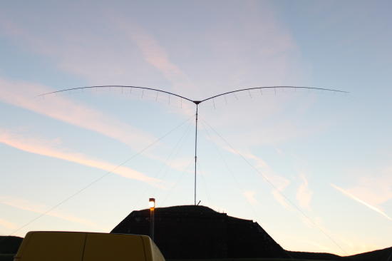
My “batwing” antenna was designed to cover the 15m, 20m, 40m and 80m bands for the SSB field day. The rules for the restricted section of that contest call for a single antenna, a maximum height limitation, and the use of no more than two antenna supports. A dipole for 80m is large: approx. 40 metres (132 feet) long. If the centre is elevated in an inverted “V” configuration, the sides will slope at a shallow angle and much of the sides will be close to the ground. If the two ends are elevated, then the balun and coax feed will have to be supported by tension in the antenna and will realistically get close to the ground. The antenna I've created performs excellently, and has a very distinctive appearance. Here is a dawn photograph!
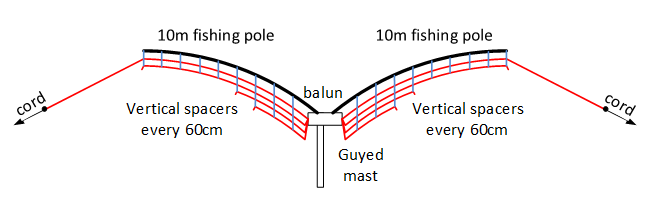
My design has two 10 metre fibreglass fishing poles at the antenna centre. This has the effect of elevating half of the 80m dipole, and all of the others, to the height of the centre support, in return for a more complex mechanical arrangement. The outer halves of the 40m antenna are stretched outwards in an inverted V form, but because half the element is supported by the fishing poles the remainder is well above ground.
At the centre, a wooden frame mounts to the mast and supports two pieces of timber that go inside the first section of the fishing poles. The timber pieces extend around 75cm into the poles. For my fishing poles, I was able to use 34x34mm timber with its corners rounded off by belt sander. They angle upwards at around 20 degrees, so that the poles have arced to being about level at their ends under their own weight.
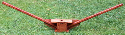 |
The centre frame - made from 34x34mm softwood and 12mm ply. This is approx 1.5m from side to side. |
The 4 individual dipoles each have to be spaced apart to keep them from interacting with each other. A distance apart of 25cm seems to work OK. I used light, thin plastic tube from B&Q; the tubes attach onto the fishing pole using cable ties. I used tubes spaced apart by around 600mm, which seems to be sufficient.
The wire dipoles are cut from 24/0.2mm PVC coated wire and then threaded through holes drilled in the support tubes. They all join together at the antenna centre, and attach to a balun there fed by coax. The outer half of the 80m dipole was made from thinner, 7/0.2mm PVC coated wire to reduce weight. The current reduces along the diploe, so this makes little performance difference. So that the whole lot can be dismantled and reassembled, I used hot melt glue to secure the dipole strands into the holes through the supports; but there may well be better solutions!
One of the problems with fan dipoles is cutting the elements to length, because they interact with each other. My approach was to make them all too long, then measure all resonant frequencies using an antenna analyser. A spreadsheet was used to estimate the amount to remove; I then removed about 90% of that amount and tried again. I didn’t find too much coupling, but it did take around 5 visits to get it all correct.
Your elements will, for various reasons, need to be a bit different in length from mine – so make it too long then trim. My element lengths, measured from the balun connection, are:
|
Band |
Wire length (each side) mm |
|
15m |
3400 |
|
20m |
5105 |
|
40m |
10140 |
|
80m |
18610 |
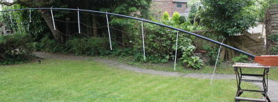 |
One side of the dipole after assembly. The tubes do eventually hang vertically but you may need to adjust the wire positions. The ends of the 80m dipole double as guy roles to prevent the antenna turning on the breeze. |
There’s no reason why a 10m dipole couldn’t be added: but I figured that the fishing poles would be broken before the sunspot activity makes it necessary!
The achieved performance is listed in the table below. The VSWR on 15 metres is limited by the balun; otherwise the VSWR performance is excellent. The antenna tunes easily with an internal ATU.
| Band |
Mid point frequency (MHz) |
Mid point VSWR |
Lower 3:1 VSWR Frequency (MHz) |
Upper 3:1 VSWR Frequency (MHz) |
| 15m | 21.096MHz | 1.6 | 20.665 | 21.800 |
| 20m | 14.210 | 1.0 | 13.942 | 14.6 |
| 40m | 7.073 | 1.2 | 6.93 | 7.21 |
| 80m | 3.66 | 1.1 | 3.5 | 3.778 |
Finally - the real test is DX performance. In the setup before the contest we were able to work China, Japan and Taiwan, with 100W from a hilltop location. Not bad.