A bit of a "proof of principle": could I design from scratch a frequency counter? 30 years ago the appropriate design route was to use an Intersil IC7216 (as I recall) counter timer chip: but somewhere along the way these have been completely displaced by microcontroller based designs. The PIC series of microcontrollers are able to implement a true "single chip" frequency counter that will work to beyond 40MHz; but all of my design experience is with the Atmel AVR family, whose timer counters won't operate at that speed... so what could I do?
The final design uses an ATTINY84 microcontroller coupled to a simple 16x2 LCD display. Because the microcontroller's counters can't count with a particularly fast clock, I used a 74AC161 4 bit synchronous counter as a prescaler. The result is a simple 2 IC design that counts beyond 100MHz.
A late addition "add on" is a power measurement function using an AD8307 log amp. This device has a huge theoretical bandwidth & dynamic range, and is easy to use.
How it works
The heart of the counter is the 8 bit microcontroller, IC4. This packs a lot of functionality into its 14 pin package. The chip includes the frequency reference oscillator: this is controlled by crystal XL1 with a common frequency “pulling” arrangement for fine calibration.
The power measurement functionality is provided by IC2 this is a logarithmic amplifier: it gives an output voltage proportional to the input power. The device has a theoretical bandwidth of around 500MHz, well beyond the expected performance of the rest of the counter. The output voltage from pin 4 is directly measured by an analogue-to-digital converter input in the microcontroller; the software averages several values to improve accuracy.
TR1 provides buffering and gain for the RF input to the counter. IC3 is a 4 bit counter, configured as a divide-by-16 prescaler. It counts cycles of the RF input signal when enabled by the microcontroller; Its divide-by-16 output clocks the counters in the microcontroller. The result is a counter capable of operating at around 100MHz, while the microcontroller itself needs count only at around 6MHz rate.
In operation, the microcontroller continually runs through a sequence of measure frequency – measure power – calculate and display. The microcontroller’s Counter/Timer 0 counts out the required “gate” period (this can be selected from 1/16, ¼ or 1 second). While the gate period is counted, the prescaler is enabled by a high level on its ENP pin and its outputs change state at 1/16 of the input clock rate. Counter/timer 1 counts these clocks. The software (hopefully!) drives the ENP signal with the exact timing required so that the count happens for the exact period. At the end of the count period, the software reads the residual count from the prescaler giving the total number of input RF cycles during the gate period.
LCD1 provides the frequency display, driven by the microcontroller. The display contrast/viewing angle is set by RV1 which needs to be adjusted to provide a comfortable display.
The Design
Download schematic: {phocadownload view=file|id=14|target=s}
The parts list is as follows:
|
Component |
Description |
Suggested source / Part number |
|
C1, C2, C3, C9, C10 |
100nF 50v ceramic capacitor |
|
|
C4-C6 |
1nF 50v ceramic capacitor |
|
|
C7 |
22pF 50v ceramic capacitor |
|
|
C8 |
10pF 50v ceramic capacitor |
|
|
VC1 |
22pF trimmer capacitor |
|
|
X1 |
16MHz crystal |
|
|
R1 |
4.7R 0.25W carbon film |
|
|
R2 |
2K2 0.25W carbon film |
|
|
R3 |
470R 0.25W carbon film |
|
|
R4 |
47K 0.25W carbon film |
|
|
R5 |
4K7 0.25W carbon film |
|
|
R6 |
330R 0.25W carbon film |
|
|
R7 |
1K 0.25W carbon film |
|
|
R8 |
33K 0.25W carbon film |
|
|
R9 |
56R 0.25W carbon film |
|
|
R10 |
220R 0.25W carbon film |
|
|
RV1 |
10K preset resistor |
|
|
IC1 |
78L05 5v regulator |
e.g. Rapid Electronics 47-3612 |
|
IC2 |
AD8307 log amplifier |
e.g. Farnell 107-9309 |
|
IC3 |
74AC161 counter |
e.g. Farnell 110-2991 |
|
IC4 |
ATTINY48A-20PU microcontroller (requires programming) |
e.g. Rapid Electronics 73-5120 |
|
IC4_SKT |
14 pin IC socket |
|
|
LCD1 |
2 row x 16 character LCD display |
e.g. Rapid Electronics 57-2224 |
|
TR1 |
BF199 or similar RF NPN transistor |
|
|
LCD1_header pins |
13 pin 0.1” pitch single row header, |
|
|
LCD1_header socket |
13 pin 0.1” pitch single row header socket |
|
|
SW1 |
Push-to-make switch |
|
|
J1 |
PP3 battery connector |
|
|
J2 |
BNC socket |
The only expensive component is the log amp, IC2 costing approximately £13 one-off. This could be omitted at first assembly if required.
Construction
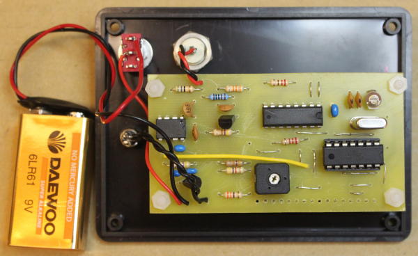
The first prototype was constructed on veroboard, and operated up to 62MHz. I concluded that was nearly, but not quite, fast enough. I've since made a single sided PCB, and that version counts to beyond 100MHz. The PCB houses all the main components. Ideally it would have been double sided, but that would make home etching much trickier; there are a number of wire links needed as a consequence. A ground plane has been used in the RF input area. All components are leaded and present no assembly worries.
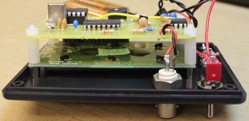
For final assembly, the PCB sits behind the LCD display and is connected via a strip of 0.1” pitch header pins and mating socket. The connectors are cut to required length from a longer strip and soldered to rear of LCD and the rear of the PCB, making a direct plug-in connection. It doesn’t matter which one goes to which PCB, but check the alignment before assembly! At a pinch, direct wire links could also be used but that would make access for rectification of any problems awkward.
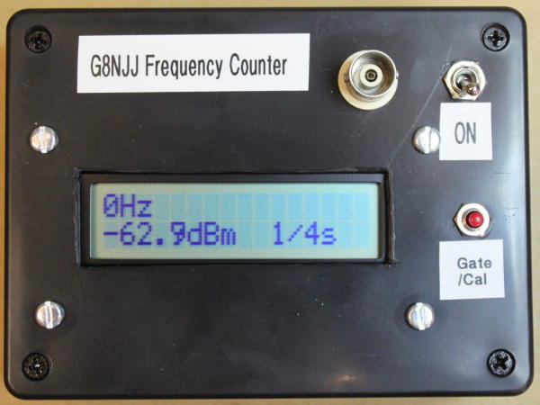
The unit has been assembled in a simple plastic case. The RF input should be connected to the front panel BNC connector via a short length of coax cable. Flying leads connect to the push switch SW1. The power feed is from a PP3 battery clip via a toggle or slide on/off switch.
The microcontroller will need programming before use. I can provide the necessary files; but HDARC members might also contact me direct and I’ll arrange to provide a programmed device.
 Download artwork: {phocadownload view=file|id=13|target=s} These are full size and can be printed to acetate etc. There are 3 pages: the copper side view, the top side view showing the links required and a colour version showing the complete assembly with component positions. For the copper links: ignote the width; simple tinned copper wire is fine for all of them.
Setting Up
RV1 should be adjusted to produce a legible display: it will be near one end of travel.
The unit requires no significant commissioning. As shipped it should be reasonably accurate; fine frequency errors can be adjusted out using VC1. If necessary coarse frequency errors and amplitude errors can be adjusted using the calibration process.
Software
The software is written entirely in "C". It is responsible for timing the "gate" period, and counting input pulses during the gate period. These functions use the microcontroller's internal timer. After frequency measurement is complete, the signal power is measured using the microcontroller's ADC; the counter prescaler is held in reset to minimise interference during the power measurement. Finally all measurements are displayed in the LCD.
The counter allows 3 different "gate" periods (1 second, 1/4s and 1/16s) to allow some choice of accuracy vs update rate. A pushbutton changes between them.
The counter has a simple calibration capability, allowing a single amplitude offset to be chosen and a frequency offset to be chosen. To enter calibration mode, press and hold the button for 1 second; the amplitude offset (in units of 0.1dBm) can then be chosen by pressing the button enough times to show the value required. When the required value is displayed, press and hold the button again for 1 second; you can then enter a frequency offset in multiples of 10ppm (parts per million). Press and hold the button again to exit calibration mode.
If anyone wants to evolve the design further, there's around 1K of code space remaining unused. You can get a lot of code into that 1K!
Performance
The frequency counter operates to beyond 100MHz, It counts at around -10dBm input level at low frequencies, but above 50MHz really needs closer to +10dBm.
The power meter has a useful dynamic range of around 70dB: +15dBm to -55dBm. Above +15dBm it begins to compress; below -55dBm noise begins to limit measurement. It seems to achieve +/- 0.5dB within those limits. Power measurements are flat from ~1MHz to 100MHz; there is 1dB rolloff at 130MHz.