
Our first HF antenna was a simple "longwire" endfed antenna. While it has worked, it hasn't been brilliant. I wanted a resonant, balanced antenna. I decided to have a go at a trapped dipole, just to see what would happen. After a little research I came across coaxial traps, which are easy to construct. It was only going to take a few hours, so why not? This is based heavily on the design by John DeGood, NU3E (http://degood.org/coaxtrap).
The Traps
The coaxial traps are wound onto some kind of plastic former, and behave as a parallel L/C pair. The capacitance part is from the inner-to-outer capacitance of the coax cable; the inductance is from the coax outer. The "C" depends primarily on the length of coax; the "L" depends on the diameter and length of the inductor that's formed. There's a calculator you can download to work out how much coax you need for each trap: http://www.qsl.net/ve6yp/index.html. It doesn't matter which way round you wire the traps but please make it symmetrical about the centre of the antenna. other writers have used the convention "coax centre goes towards the antenna centre". (It will affect the wire lengths used).
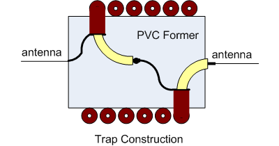
I used RG/58 coax, with a "proper" screen (not a foil layer). I've used 37mm plastic waste pipe as formers for 4 of the 6 traps, and joiners for 22mm waste pipe for the 28MHz ones. I expected a lot of cutting & retrying to get the lengths right so I was surprised to find the first one spot on. I aimed for an "in band" resonance (opinions vary as to whether that's wise). To measure the resonant frequency I've used the MFJ259 antenna analyser: simply wrap a turn of wire round the trap, and look for a high impedance. It should (and does) go off the scale. You can tune the trapsby spreading out the coax turns to lower the resonant frequency.
| Frequency | 14.175MHz | 21.225MHz | 28.9MHz |
| Diamter of former | 37mm | 37mm | 26mm |
| Coax length | 900mm | 650mm | 510mm |
| inductor length | 32.7mm | 23.3mm | |
| no. turns | 6.7 | 4.8 | 5.1 |
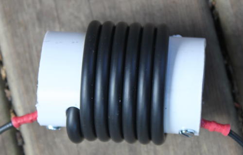
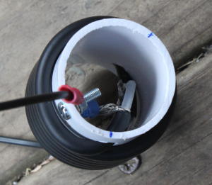
To finish the traps, I've wrapped the outer in self amalgamating tape. This is mostly to hold the coax in place. I sealed the ends of the coax using silicone sealant; I don't yet know whether that's up to the job or not. The wire segments of the antenna connect using M3 screws at each end.
The Antenna Segments
The wire elements for the antenna are simple 32/0.2mm stranded copper wire with PVC insulation. That's a conductor area of 1mm2 - quite enough. I've used crimp ring terminals to connect the elements at each end; the lengths are from end of ring to end of ring. These measurements were made after tuning: ideally cut all the wires slightly too long, then beginning from the insude (10m band) segment, cut them to size to get the VSWR minimum at mid-band. An antenna analyser makes this easy.
 (only one limb of antenna shown)
The Balun
There's then the question of a suitable balun. I had a T200-2 (red) toroid, which is exactly the right component. Be careful where you get your design: the first one I copied was from a UK web page, and was NOT wired as a balun. To test it, I connected a 50Ω resistor where the antenna would go; the MFJ259 consistently saw 25Ω. Worse, when testing the antenna it was very clear that there was RF on the coax outer: if you touched it, the VSWR changed a lot. That's exactly what a balun should stop from happening!
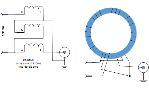
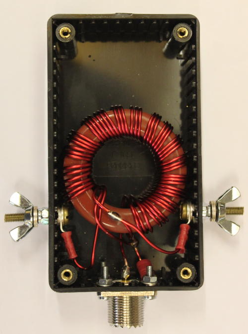
The revised version follows the same design as in the Radio Communication Handbook, and the ARRL handbook. I've used the version with 3 windings, resulting in both antenna elements being DC grounded (good to avoid static problems). I used 18 turns on the toroid core. with the 50Ω test resistor the impedance was fine at low frequencies but seemed to be quite reactive at higher frequencies (15+ MHz). Most designs suggest 14 turns or so, so I may have used too many? Nevertheless, it's the performance as an antenna that counts.
| Band | Resonance |
2:1 VSWR (MHz) |
3:1 VSWR (MHz) |
| 40 m |
7.05MHz (1.2:1) |
6.95-7.15 | 6.8-7.23 |
| 20 m |
14.130MHz (1.2:1) |
14.057-14.198 | 13.9-14.262 |
| 15 m |
21.07MHz (1.0:1) |
20.88-21.24 | 20.7-21.45 |
| 10 m |
27.5MHz (1.1:1) |
27.0-28.05 | 26.5-28.8 |
| 6 m | ~51MHz | 50-52MHz | not tested |
Clearly the antenna is too long at 10 metres, and would benefit from a slight upward movement in frequency everywhere. Removing a little length from the centre conductors looks the next step. However: as a first attempt it looks pretty good.
Instantly my FT450D's internal ATU can tune the antenna at any point I tried. I hadn't expected it to work on 6m, but it does seem to load OK.