
This is a design for a very simple antenna you can make yourself. About the simplest antenna you can have is a dipole antenna, made from two "arms" with a total length of half a wavelength. The dipole can be a very effective antenna, but operates on only one band.
To make a multi-band dipole, a simple solution is to split it into sections with some way to connect them to choose bands. I've made a simple dipole for 4 HF bands, using crocodile clips to join across gaps at each band end. By selecting segments with the croc clips, the antenna can be selected for 10m, 15m, 20m or 40m bands.
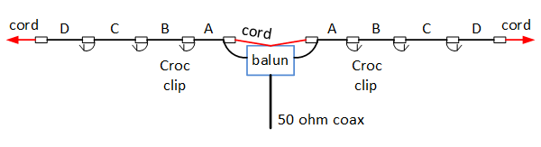
The wire used isn't very critical: the key point is to make sure it's strong enough to support itself. For my dipole the elements are made from 24/0.2mm PVC insulated, stranded wire: I bought a large roll of it at the National Hamfest specifically for making wire antennas. At the centre, strain reliefs take the tension off onto nylon rope that clips onto the balun using split ring key rings; the wire then connects to the balun terminals with a little slack. At the other end, insulators allow a nylon rope or string to be attached to support the ends. The joins between the bands are made using a piece of PVC strip: the wire is tied off to the end, then connects to a pair of screws with croc clips to join as required. The centre of the dipole needs to be fed by a balun. There is a simple balun design elsewhere on this site.
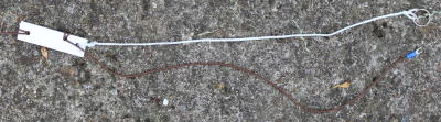 |
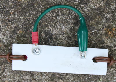
At the balun, a piece of nylon cord acts as a strain relief. I used keyring type split rings to clip them onto a metal loop on the balun box.The insulator to the antenna wire is a piece of PVC strip from B&Q. |
 |
The joint between two segments: a piece of PVC strip acts as the insulator. The dipole ends join to a screw & nut at each end; a croc clip is used to make the connection between segments. Clip the croc clip to the unused screw when the segments aren't connected. |
The exact lengths of wire required will depend on how close to the ground the antenna is, how you do the strain reliefs, and the lengths of the crocodile clip wire lengths etc. Make it 10% longer, then adjust. I adjusted mine by starting with the centre section and using an MFJ259 antenna analyser to find the resonant frequency and cut as needed to get the band centres right. Thereafter, the VSWR across bands is well within the tuning range of most modern auto ATUs.
| Band | Segments | Length total (m) |
| 10M | A | 2.300 |
| 15M | A,B | 3.090 |
| 20M | A,B,C | 4.610 |
| 40M | A,B,C,D | 9.230 |
So far I've used the dipole in an "inverted V" configuration, with the balun and coax supported by a fibreglass mast and the wire elements sloping downwards toward the ground. You can "hang" the dipole and coax with the antenna supported at the two ends, but it would be a substantial load and would be prone to sagging. I'm able to get a VSWR at mid-band of 1.2:1 or less except on 10 metres, where the mid-band VSWR is around 1.6:1. This is because the balun is at its upper frequency limit It's possible that a ferrite one may improve that.
The centre of a dipole antenna has an impedance of around 72 ohms, which is reasonably close to the 50 ohm impedance of modern transceivers. However, each of the two "arms" of a dipole radiate - neither is grounded. Consequently, you shouldn't just feed a dipole from coax: you should use a balun.
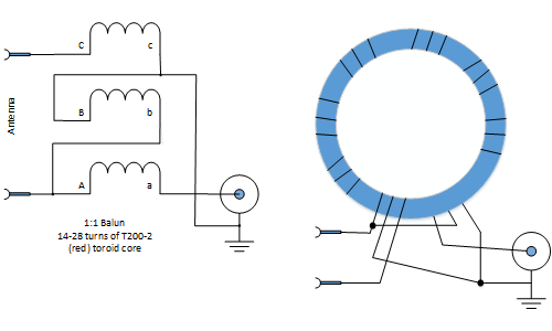
A balun is simply an RF transformer. There are several types of balun, and a lot of argument about which of them really work: however to feed a simple dipole, what you need is a 1:1 current balun. Nowadays there are made by winding copper wire onto a ferrite or dust iron core.
To cover the HF bands, you can make a simple balun using a T200-2 Dust iron Toroidal core and enamelled copper wire. You will need to use reasonably large diameter wire - e.g. 16SWG. This core and wire size will cope with 100W SSB. If in doubt, transmit for a few seconds and see if the core gets warm: if so, you need a larger core.
A balun is a relatively broadband device: however the number of turns used affects the frequency range the balun will operate efficiently over. With too few turns, the core won't magnetise sufficiently at low frequencies. With too many turns, it will become reactive at high frequencies. Around 17 turns of enamelled copper wire gives a reasonable compromise.
It's important to get the windings joined together correctly - look carefully at the diagram!
With a switched dipole I'm able to get a VSWR at mid-band of 1.2:1 or less except on 10 metres, where the mid-band VSWR is around 1.6:1. This is because the balun is at its upper frequency limit. It's possible that a ferrite one may improve that.
The simplest form of antenna is the dipole. It has good performance and isn’t dependent upon a ground. However, it does only work effectively at one frequency. Although a dipole cut for an HF band can easily be matched over that band, it can’t easily be matched for a different band. Its feedpoint impedance on the frequency it is cut for will be around 72 ohms; on other bands it will have a much higher impedance.
Many people want antennas that cover more than one band. A fan dipole is a simple concept: connect several dipoles together at the feedpoint. The result is an antenna that works well over as many bands as you have dipoles. There are two principal downsides: it is more complicated mechanically, and can be tricky to adjust onto the required frequencies.
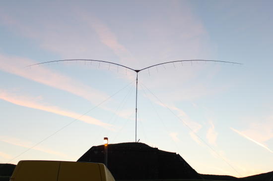
My “batwing” antenna was designed to cover the 15m, 20m, 40m and 80m bands for the SSB field day. The rules for the restricted section of that contest call for a single antenna, a maximum height limitation, and the use of no more than two antenna supports. A dipole for 80m is large: approx. 40 metres (132 feet) long. If the centre is elevated in an inverted “V” configuration, the sides will slope at a shallow angle and much of the sides will be close to the ground. If the two ends are elevated, then the balun and coax feed will have to be supported by tension in the antenna and will realistically get close to the ground. The antenna I've created performs excellently, and has a very distinctive appearance. Here is a dawn photograph!
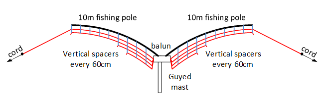
My design has two 10 metre fibreglass fishing poles at the antenna centre. This has the effect of elevating half of the 80m dipole, and all of the others, to the height of the centre support, in return for a more complex mechanical arrangement. The outer halves of the 40m antenna are stretched outwards in an inverted V form, but because half the element is supported by the fishing poles the remainder is well above ground.
At the centre, a wooden frame mounts to the mast and supports two pieces of timber that go inside the first section of the fishing poles. The timber pieces extend around 75cm into the poles. For my fishing poles, I was able to use 34x34mm timber with its corners rounded off by belt sander. They angle upwards at around 20 degrees, so that the poles have arced to being about level at their ends under their own weight.
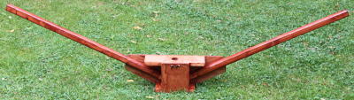 |
The centre frame - made from 34x34mm softwood and 12mm ply. This is approx 1.5m from side to side. |
The 4 individual dipoles each have to be spaced apart to keep them from interacting with each other. A distance apart of 25cm seems to work OK. I used light, thin plastic tube from B&Q; the tubes attach onto the fishing pole using cable ties. I used tubes spaced apart by around 600mm, which seems to be sufficient.
The wire dipoles are cut from 24/0.2mm PVC coated wire and then threaded through holes drilled in the support tubes. They all join together at the antenna centre, and attach to a balun there fed by coax. The outer half of the 80m dipole was made from thinner, 7/0.2mm PVC coated wire to reduce weight. The current reduces along the diploe, so this makes little performance difference. So that the whole lot can be dismantled and reassembled, I used hot melt glue to secure the dipole strands into the holes through the supports; but there may well be better solutions!
One of the problems with fan dipoles is cutting the elements to length, because they interact with each other. My approach was to make them all too long, then measure all resonant frequencies using an antenna analyser. A spreadsheet was used to estimate the amount to remove; I then removed about 90% of that amount and tried again. I didn’t find too much coupling, but it did take around 5 visits to get it all correct.
Your elements will, for various reasons, need to be a bit different in length from mine – so make it too long then trim. My element lengths, measured from the balun connection, are:
|
Band |
Wire length (each side) mm |
|
15m |
3400 |
|
20m |
5105 |
|
40m |
10140 |
|
80m |
18610 |
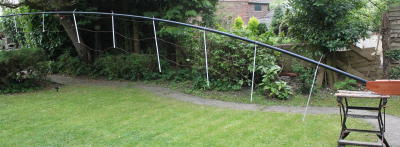 |
One side of the dipole after assembly. The tubes do eventually hang vertically but you may need to adjust the wire positions. The ends of the 80m dipole double as guy roles to prevent the antenna turning on the breeze. |
There’s no reason why a 10m dipole couldn’t be added: but I figured that the fishing poles would be broken before the sunspot activity makes it necessary!
The achieved performance is listed in the table below. The VSWR on 15 metres is limited by the balun; otherwise the VSWR performance is excellent. The antenna tunes easily with an internal ATU.
| Band |
Mid point frequency (MHz) |
Mid point VSWR |
Lower 3:1 VSWR Frequency (MHz) |
Upper 3:1 VSWR Frequency (MHz) |
| 15m | 21.096MHz | 1.6 | 20.665 | 21.800 |
| 20m | 14.210 | 1.0 | 13.942 | 14.6 |
| 40m | 7.073 | 1.2 | 6.93 | 7.21 |
| 80m | 3.66 | 1.1 | 3.5 | 3.778 |
Finally - the real test is DX performance. In the setup before the contest we were able to work China, Japan and Taiwan, with 100W from a hilltop location. Not bad.
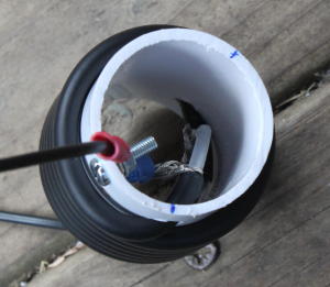
This is a “coaxial collinear” based on the design from John, VK2ZOI (see http://vk2zoi.com/articles/dual-band-high-gain-flower-pot/). See the original article for more details.
The antenna is constructed from RG58/U coax, 22mm plastic plumbing (waste) pipe and aluminium cooking foil. It’s simple and cheap to construct, and seems to have fair performance. Unfortunately it needs some “original thinking” on the mechanical perspective, but that’s probably quite easily fixed.
Electrically, the antenna consists of two half wave elements at 2m stacked one above the other; a piece of coax in the middle inserts a half wavelength phase shift to make the second half radiate effectively. At 70cm each radiating element is one-and-a-half wavelengths, and a foil “outer” makes the whole behave as four stacked half wavelengths. There are two possible explanations as to how all of this works, of which I prefer the second:
- Because all of the elements produce a solution to the electromagnetic field equations at the correct centre frequencies;
- “It just does”.
John describes the antenna as a prototype, unproven design. I constructed the first version exactly as described, and found that it operated on both bands but wasn’t ideally matched on either (with VSWR ~2.2 on 2m; I can’t measure calibrated VSWR on 70cm). It also appeared, using an antenna analyser, that it was trying to resonate on two different frequencies.
Could I do better? I checked all the element lengths using a simple spreadsheet, using 95% velocity factor for wire and 66% for RG58/U coax. That suggested the antenna was nearly 20cm too short – enough to make a difference. I remade the antenna and found its VSWR was excellent – dipping to perhaps 1.2 on 2m and “no bars shown” on the FT817 on 70cm. That’s as good as you are likely to get on a collinear without a lot more work.
The antenna is made from a piece of RG58/U coax. Mine was made with cable from Nevada Radio; other brands may have slightly different velocity factor and need different lengths. You will need at least 5m of coax to begin!
The dimensions shown are for the mark 2, “correct” lengths.
It requires the PVC outer and braid removing from the coax in two places, leaving the PTFE centre insulator intact. Use a sharp knife to remove the outer, then side cutters to “nip” the braid until freed at both ends; it can then be bunched up and slid off. I used heatshrink sleeving to seal the joins.
Keep the removed braid for the next heavy duty earth strap you need!
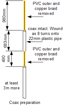
The coax is “assembled” on a 2.5m piece of 22mm plastic waste pipe. In two places the coax is close wound onto the outside of the pipe; it then threads inside the pipe for the intermediate sections. Some careful work with a 6.5mm drill and a pair of tweezers will pay off here!
Finally two pieces of aluminium cooking foil are glued / taped onto the outside of the tube in the positions shown. They are each 235mm long. In principle they can be slid up or down to optimise VSWR, but I found that only gross changes made any difference.
The foil will need to be protected, and the holes into the pipe need to be sealed. You can get heat shrink sleeving big enough to do that, but it is getting pricey (it will comfortably double the cost). Alternatively use carefully wound self amalgamating tape over the two chokes and the foil.
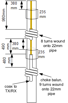
The “middle” piece of coax that is wound onto the pipe is a phasing section. The bottom section is a choke balun: above it the coax outer deliberately radiates, while below the choke it acts as a normal coax feeder. You can test whether it has been effective by holding the coax near the TX end and seeing if the VSWR changes. Only do this at low power though!
Electrically, my mark 2 version works well. Where it fails is in mechanical design: it is around 2.2m long and the PVC plumbing pipe is just too flexible. I’d like it if the antenna lasts longer than a day, but put up on a roof in a breeze it might not make that!
A credible structure might be possible using one of the telescopic fibreglass “roach pole” type fishing rods. A posh carbon fibre one would be no good (it would be conductive) but fibreglass ones are readily available. I’m not sure if they retain strength if drilled; some reinforcing may be needed.
I’ve moved on to other projects for the moment, so it will be a while before I do any more with this. Does anyone else want to pick up the cudgels and have a go at finishing this?
Our first HF antenna was a simple "longwire" endfed antenna. While it has worked, it hasn't been brilliant. I wanted a resonant, balanced antenna. I decided to have a go at a trapped dipole, just to see what would happen. After a little research I came across coaxial traps, which are easy to construct. It was only going to take a few hours, so why not? This is based heavily on the design by John DeGood, NU3E (http://degood.org/coaxtrap).
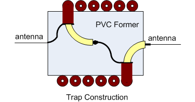
The Traps
The coaxial traps are wound onto some kind of plastic former, and behave as a parallel L/C pair. The capacitance part is from the inner-to-outer capacitance of the coax cable; the inductance is from the coax outer. The "C" depends primarily on the length of coax; the "L" depends on the diameter and length of the inductor that's formed. There's a calculator you can download to work out how much coax you need for each trap: http://www.qsl.net/ve6yp/index.html. It doesn't matter which way round you wire the traps but please make it symmetrical about the centre of the antenna. other writers have used the convention "coax centre goes towards the antenna centre". (It will affect the wire lengths used).
I used RG/58 coax, with a "proper" screen (not a foil layer). I've used 37mm plastic waste pipe as formers for 4 of the 6 traps, and joiners for 22mm waste pipe for the 28MHz ones. I expected a lot of cutting & retrying to get the lengths right so I was surprised to find the first one spot on. I aimed for an "in band" resonance (opinions vary as to whether that's wise). To measure the resonant frequency I've used the MFJ259 antenna analyser: simply wrap a turn of wire round the trap, and look for a high impedance. It should (and does) go off the scale. You can tune the trapsby spreading out the coax turns to lower the resonant frequency.
| Frequency | 14.175MHz | 21.225MHz | 28.9MHz |
| Diamter of former | 37mm | 37mm | 26mm |
| Coax length | 900mm | 650mm | 510mm |
| inductor length | 32.7mm | 23.3mm | |
| no. turns | 6.7 | 4.8 | 5.1 |
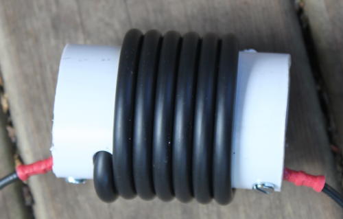
To finish the traps, I've wrapped the outer in self amalgamating tape. This is mostly to hold the coax in place. I sealed the ends of the coax using silicone sealant; I don't yet know whether that's up to the job or not. The wire segments of the antenna connect using M3 screws at each end.
The Antenna Segments
The wire elements for the antenna are simple 32/0.2mm stranded copper wire with PVC insulation. That's a conductor area of 1mm2 - quite enough. I've used crimp ring terminals to connect the elements at each end; the lengths are from end of ring to end of ring. These measurements were made after tuning: ideally cut all the wires slightly too long, then beginning from the insude (10m band) segment, cut them to size to get the VSWR minimum at mid-band. An antenna analyser makes this easy.
 (only one limb of antenna shown)
The Balun
There's then the question of a suitable balun. I had a T200-2 (red) toroid, which is exactly the right component. Be careful where you get your design: the first one I copied was from a UK web page, and was NOT wired as a balun. To test it, I connected a 50Ω resistor where the antenna would go; the MFJ259 consistently saw 25Ω. Worse, when testing the antenna it was very clear that there was RF on the coax outer: if you touched it, the VSWR changed a lot. That's exactly what a balun should stop from happening!

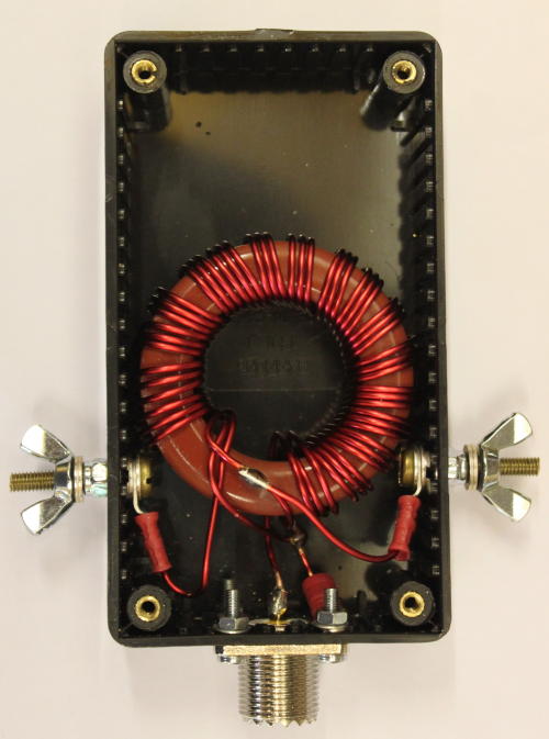
The revised version follows the same design as in the Radio Communication Handbook, and the ARRL handbook. I've used the version with 3 windings, resulting in both antenna elements being DC grounded (good to avoid static problems). I used 18 turns on the toroid core. with the 50Ω test resistor the impedance was fine at low frequencies but seemed to be quite reactive at higher frequencies (15+ MHz). Most designs suggest 14 turns or so, so I may have used too many? Nevertheless, it's the performance as an antenna that counts.
| Band | Resonance |
2:1 VSWR (MHz) |
3:1 VSWR (MHz) |
| 40 m |
7.05MHz (1.2:1) |
6.95-7.15 | 6.8-7.23 |
| 20 m |
14.130MHz (1.2:1) |
14.057-14.198 | 13.9-14.262 |
| 15 m |
21.07MHz (1.0:1) |
20.88-21.24 | 20.7-21.45 |
| 10 m |
27.5MHz (1.1:1) |
27.0-28.05 | 26.5-28.8 |
| 6 m | ~51MHz | 50-52MHz | not tested |
Clearly the antenna is too long at 10 metres, and would benefit from a slight upward movement in frequency everywhere. Removing a little length from the centre conductors looks the next step. However: as a first attempt it looks pretty good.
Instantly my FT450D's internal ATU can tune the antenna at any point I tried. I hadn't expected it to work on 6m, but it does seem to load OK.