
I needed a VHF and ideally UHF portable antenna. I had been assuming that meant lots of clever metalwork. But clever people have provided much more elegant solutions!
I made the coax cable based antenna for 2m and 70cm as described for RAYNET use by G3SMW. I believe the original designer was Frank Bremer, PA0FBK. This is made from approx 1.2m of RG58 coax, it has a small tuning stub then an RG58 feeder "tail" that includes a choke made by winding the coax into a coil. The antenna behaved as advertised, except I had to trim mine shorter than expected to get "good enough" VSWR on 2m. I achieved ~1.7:1; the antenna analyser suggests it is much better at about 139MHz. I don't have a calibrated way to measure VSWR on 70cm, other than to measure "3 bars" on the FT817 display. I threaded a nylon cord alongside the coax, that ends in a split ring type key ring.
For portable use I purchased a 6m fibreglass telescopic rod. These seem to be comonly known as "roach poles". Clever creatures, these fish. Mine actually came from a company called Wind Creations who sell them as freestanding poles for banners. A 6m pole, a 1m fibreglass ground spike to hold it upright and a bag cost approx £20 and weighs less than 1kg. The antenna fits into the same bag.
We were able to hand carry the whole lot up Butser Hill near home and operate /P for the first time today. It takes around a minute to erect the mast and antenna; it can easily be done single handed.
I wanted a simple "get me started" antenna for VHF. I thought I'd had a bright idea in using copper plumbing pipe but it quickly proved to be a very well known method. But in looking for a suitable antenna I came across the J-pole.
I took the basic design from Dale Kubichek, N6JSK web page. I reproduced the metalwork exactly as described. To mount the SO239 connector I used a "jubilee" clip with the end folded out; I used another to clamp the other end of the feed wire.
When rested with an MFJ antenna analyser, the match on 2 metres wasn't great. No problem; the great thing about the analyser is you can find out where the resonances are. Mine were at about 151MHz so I was able to calculate the "extra" length required and join a little more pipe to the antenna. I also optimised the feed positions to get about 1.1:1 VSWR.
Unfortunately, these changes meant the antenna would not work at all on 70cm. My analyser doesn't go that far, so I've no idea what changes are needed. I decided to call it a day and have a working VHF antenna, rather than a non working dual band one.
Our first antenna: a simple HF "long wire" antenna.
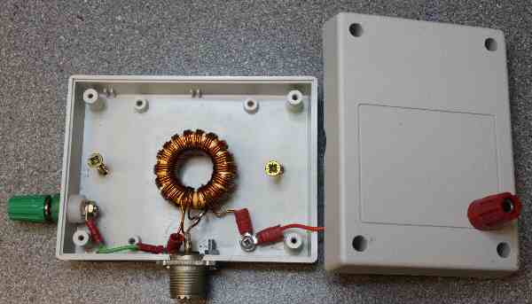
The antenna itself is a 63 foot length of multi-strand copper wire, running from the shack at one end to the eaves of the house at the other. It is approximately 15 feet above ground. Antennas of that sort are usually high imedance at the feed point. I have used a 9:1 "unun" impedance transformer. The inspiration for my design came from John, M0UKD's web page. Mine has 17 turns trifilar wound on a T130-6 toroid core. Ideally it would have had one or two more turns, but the core can only take so much wire and I didn't plan ahead....
The earth is a 1 metre long ground spike. I doubt that it is very high quality. For reasons of RF safety I put the transformer above head height because people will walk past it; that means there is approx 2.4 metres of wire from ground to the transformer. That's almost a quarter wave long at 28MHz. Ideally the transformer should be at ground level, and some users put the antenna wire in a plastic pipe to preserve RF safety.
Using an MFJ antenna analyzer I measured the following impedance and SWR values in the shack:
| Frequency | VSWR | Impedance |
| 1.85 | 10.3 | R=89 X=177 |
| 3.65 | 3.9 | R=19 X=48 |
| 7.05 | 14 | R=8 X=35 |
| 10 | 9.1 | R=25 X=87 |
| 14.2 | 4.5 | R=41 X=67 |
| 18 | 3.7 | R=2- X=32 |
| 21.2 | 4.6 | R=10 X=41 |
| 24 | 6.9 | R=8 X=15 |
| 29 | 3.5 | R=31 X=44 |
| 51 | 8.4 |
R=227 X=156 (unlikely to work well) |