
This is a design for a very simple antenna you can make yourself. About the simplest antenna you can have is a dipole antenna, made from two "arms" with a total length of half a wavelength. The dipole can be a very effective antenna, but operates on only one band.
To make a multi-band dipole, a simple solution is to split it into sections with some way to connect them to choose bands. I've made a simple dipole for 4 HF bands, using crocodile clips to join across gaps at each band end. By selecting segments with the croc clips, the antenna can be selected for 10m, 15m, 20m or 40m bands.
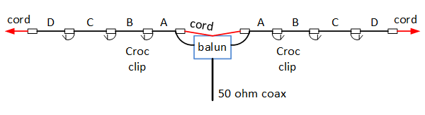
The wire used isn't very critical: the key point is to make sure it's strong enough to support itself. For my dipole the elements are made from 24/0.2mm PVC insulated, stranded wire: I bought a large roll of it at the National Hamfest specifically for making wire antennas. At the centre, strain reliefs take the tension off onto nylon rope that clips onto the balun using split ring key rings; the wire then connects to the balun terminals with a little slack. At the other end, insulators allow a nylon rope or string to be attached to support the ends. The joins between the bands are made using a piece of PVC strip: the wire is tied off to the end, then connects to a pair of screws with croc clips to join as required. The centre of the dipole needs to be fed by a balun. There is a simple balun design elsewhere on this site.
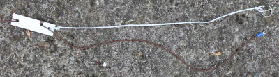 |
At the balun, a piece of nylon cord acts as a strain relief. I used keyring type split rings to clip them onto a metal loop on the balun box.The insulator to the antenna wire is a piece of PVC strip from B&Q. |
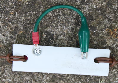 |
The joint between two segments: a piece of PVC strip acts as the insulator. The dipole ends join to a screw & nut at each end; a croc clip is used to make the connection between segments. Clip the croc clip to the unused screw when the segments aren't connected. |
The exact lengths of wire required will depend on how close to the ground the antenna is, how you do the strain reliefs, and the lengths of the crocodile clip wire lengths etc. Make it 10% longer, then adjust. I adjusted mine by starting with the centre section and using an MFJ259 antenna analyser to find the resonant frequency and cut as needed to get the band centres right. Thereafter, the VSWR across bands is well within the tuning range of most modern auto ATUs.
| Band | Segments | Length total (m) |
| 10M | A | 2.300 |
| 15M | A,B | 3.090 |
| 20M | A,B,C | 4.610 |
| 40M | A,B,C,D | 9.230 |
So far I've used the dipole in an "inverted V" configuration, with the balun and coax supported by a fibreglass mast and the wire elements sloping downwards toward the ground. You can "hang" the dipole and coax with the antenna supported at the two ends, but it would be a substantial load and would be prone to sagging. I'm able to get a VSWR at mid-band of 1.2:1 or less except on 10 metres, where the mid-band VSWR is around 1.6:1. This is because the balun is at its upper frequency limit It's possible that a ferrite one may improve that.