
My first project: a simple antenna tuner for the HF bands. The modern approach to antenna tuners seems to be to use the "T" match (a highpass construct) rather than the "Z" match (which is a lowpass filter). General wisdom seems to be to have capacitors approximately 250pF, and an inductor 25-30uH.
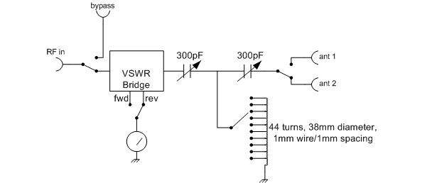
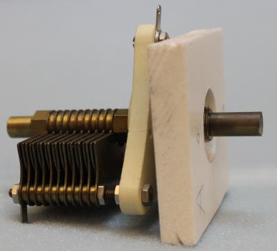
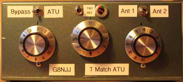
Sourcing the capacitors was a problem: I can't find anyone that makes variable capacitors any more! I purchased some from J Birkett in Lincoln, but these had very small air gaps which would limit the usable power. Eventually I found a pair of 300pF (ish) capacitors at a Rally. The "T" match design requires that the capacitors be insulated from ground. I mounted mine onto a thin piece of plastic material with a partly bored hole for the mounting nut. The knobs are calibrated 0-6, with 0 being full capacitance and 0 being exactly unmeshed.
The inductor was wound on a 5 inch piece of 38mm drain pipe using enamelled copper wire 1mm diameter. I aimed for double spacing using another piece of wire as a spacer, which was later removed. The whole was varnished to hold the wire in place. The VSWR bridge was originally to be home made, but I'd purchased a universal VSWR bridge kit while purchasing toroids and in the end I used that for convenience. I have a 10 position rotary switch - modified from a 2 pole 5 way switch giving 9 positions plus open circuit.
The conventional wisdom is that the inductor should be evenly tapped. I tried and fund that I almost never needed beyond the 12th turn, and from 14MHz I was always on the 4 turn tap. I retapped the coil with the following results, measured with an MFJ259B antenna analyser:
| Switch position | Turns | Inductance |
| 0 | 2 | 0.8uH |
| 1 | 4 | 1.6uH |
| 2 | 6 | 2.4uH |
| 3 | 8 | 3.3uH |
| 5 | 12 | 5.3uH |
| 6 | 16 | 7.5uH |
| 7 | 21 | 10.6uH |
| 8 | 27 | 14.6uH |
| 9 | 34 | 20uH |
| 4 | 44 | 29uH |
A tiny "battery indicator" moving coil meter was used for tuning indication. It isn't intended to provide a calibrated measurement. The ATU was assembled into a diecast box, and spray painted. Mysteriously the colour looks remarkably like that of my old car.
Loading into 50Ω and into my longwire antenna was as follows (recorded as C1 - L - C2):
| Frequency | 50Ω | End fed antenna |
| 1.9MHz | 0-8-0 | 1-9-3 |
| 3.65MHz | 4-7-4 | 3.5-6-3 |
| 7.05MHz | 4-4-3.5 | 4.2-3-2.5 |
| 10.1MHz | 4.5-2-4 | 3.8-1-3.8 |
| 14.2MHz | 4.5-1-4.5 | 2.5-0-3 |
| 18MHz | 2.5-0-1.8 | 4-0-0 (poor) |
| 21.2MHz | 2.8-0-1.8 | 4.5-0-0 (poor) |
| 24MHz | 2.5-0-1 | |
| 29MHz | 0.8-0-0.2 | no match |
Clearly there is a problem at high frequencies. The stray inductance makes it hard to measure the coil inductance, especially with the switch and wiring in place. The coil may need more taps down the "bottom" end, and there may not be enough steps available.
Back to the drawing board!