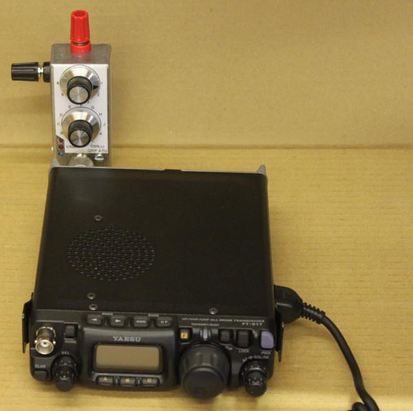
This is a very simple ATU, designed for portable operation with an FT817. There's no point having a small transceiver if you need to carry lots of kit to use it: so this was designed down to a size. I liked the "Wonder Wand" style of ATU, but thought I'd have a go at making my own.
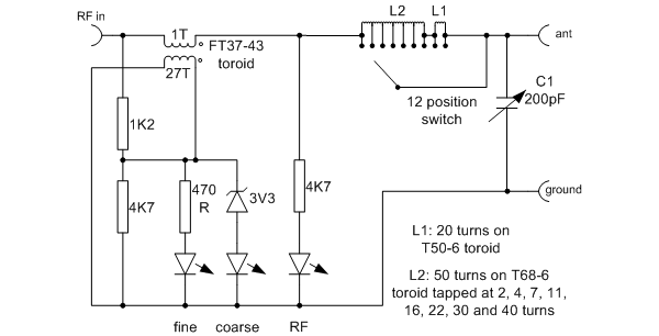
The ATU was designed to fit a 9cm x 3.5cm x 3cm diecast box. The RF input is via an SO239 connector, which connects through a male-to-male adapter straight onto the back of the FT817. An "L match" ATU circuit is used, with a 12 position tapped inductor and 200pF "polyvaricon" capacitor. Particularly because of the latter, the power is limited to a few watts maximum.
A simple LED indicating VSWR display is also used: the idea is that the LEDs light if reverse power is present, with one LED being more sensitive to allow "nulling" of reverse power. This uses the design by DF3OS.
In keeping with the "Wand" style ATU, I tried it out with a telescopic antenna. After shopping around, the longest I could get was around 1.2m which you will realise has too small an aperture to be usable on HF (although it worked nicely on 2m, and could be matched on 20m and up). A length of wire proved much better.
There is a "word of warning" with ATU design. Make sure that the switch selecting the number of turns on the inductor shorts out the unused turns. Without that, the unused part can resonate. Mine did, at 21MHz; it took a while to work out why it wouldn't load up on that band. with the unused turns shorted out, its behaviour was transformed.
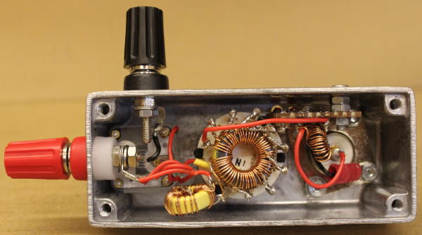
Construction
There aren't many components involved, so cunstruction is simple. Most of the inductor is wound on a T68-6 (yellow) dust iron toroid core. This has 50 turns with taps at 2, 4, 7, 11, 16, 22, 30 and 40 turns. Remember that the switch alnso needs to select the 50th turn, and the start of the coil (i.e. the "0"th turn). Because I couldn't fit all of the turns onto one core, a further 30 turns on a smaller T50-6 toroid is used to provide additional inductance if needed. With a larger toroid, it may have been possible to get it all onto one core; try a T80 or larger core and aim for 60 turns total if you wish to experiment.
The VSWR indicator circuit has a small ferrite FT37-43 core, the primary of which is just a single wire passing through the middle. It is constructed on veroboard.
I don't know how people test and calibrate ATUs. Ideally I suppose you could pake up various "test loads" with coils, capacitors and resistors and see if they match. My approach was simply to test the match into 50Ω and into a small wire antenna.
In Use
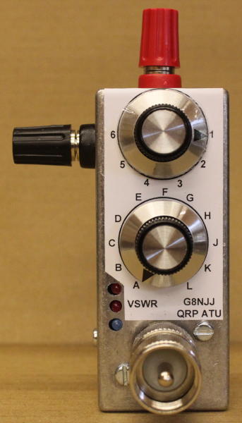
For such a simple circuit it does seem to be remarkably effective, and it is easy to use. The inductor taps are marked A-L and the capacitor is marked 1-6. The VSWR indication isn't very effective (two LEDs can never be as good as a moving meter needle, but there's no way one of those would fit the box). But what I've found very effective is to pre-measure the required settings for a 5m vertical antenna and go back to them - it is pretty repeatable. They are marked on the side of the unit with a dymo tape.
| Frequency | 50 Ω load | 5m whip antenna |
| 3.6MHz | L4 | poor! |
| 7.1MHz | L4 | C6 |
| 14.2MHz | K4 | G3 |
| 21.2MHz | J4 | G5 |
| 29MHz | K5 | G6 |
| 51MHz | K5 | H5 |