
My plan is to use the Red Pitaya board with pihpsdr and my console as the basis for the SDR processing. The Red Pitaya has two 14 bit/125MHz ADC and two 14 bit/125MHz DAC channels; so fully capable of dual receiver operation. Pavel Demin has developed suitable FPGA and ARM software. However it will need a front end. Pretty much all the HPSDR-derived software supports the "Alex" signal conditioning boards as a standard; so I will need something compatible with that. A few hours free in an airport has led to an outline design:
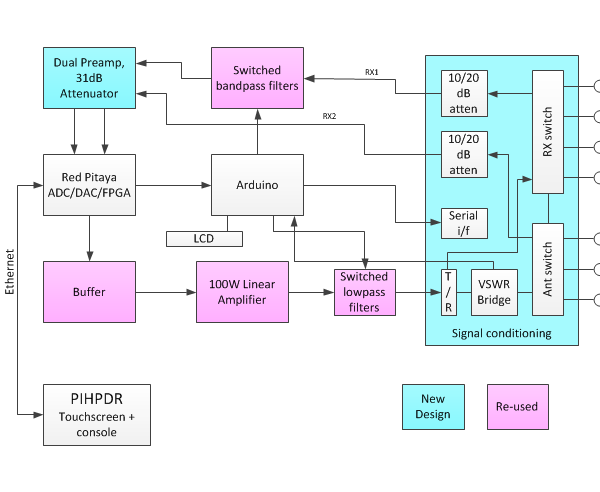
RX and Antenna switching relays - as per Alex ie 3 selectable antennas, 3 alternative RX inputs.
VSWR measurement - the same Stockton bridge as used in Alex
Signal coupler for Puresignal - use the same Stockton bridge. This will mean buffering the forward/reverse power samples before the detector diodes to make sure that no intermodulation is added to the coupled forward power signal going back to the receiver. Tentative buffer choice - Texas Instruments LMH6321 (capable of +/-12V output; likely swing +/-4.7V for 100W).
RX path - 0-31dB switched attenuator as per Hermes; probably an Analog Devices HMC624ALP4E, which is readily available in UK rather than the Minicircuits one. The ADC also needs a preamp, because the Red Pitaya's ADC driver appears to have unity gain; so a 20dB amplifier will be needed. Tentative choice: Analog Devices ADA4895 which is readily available. The Red Pitaya has a high impedance input, and others have reported issues with that. My first plan will be to solder a 50 ohm resistor across its input; if that fails having the 20dB preamp within half an inch of the input connector may avoid problems. I plan to use a set of switched bandpass filters rather than the Alex highpass/Lowpass arrangement. Several seem to be available as kits - I have the Radioshop RV3YF kit from Ebay, and I've previously assembled the Spectrum Communications unit. That's diode switched though, and the loss may be undesirable at higher frequency. A 50MHz LNA may be needed in the awitched filters; I have tentatively selected the minicircuits PSA4-5043+ (25dB gain, 0.75dB NF).
TX chain - the Red Pitaya output will need a buffer amplifier before going through a 100W PA and LPF. I plan to use a "recycled" LPF from Ebay from a scrapped transceiver. Part of the data from the PC is an 8 bit TX amplitude value, used to scale the DAC output. There's a web design with analogue control over the DAC reference current, giving around 20dB dynamic range. Alternatively I can use a 6 bit/0 to 31.5dB attenuator, but the 8 bit control value will need to be converted to a dB value. A lookup table in the Arduino will be simplest. there should also be a tapped off aux output as a transverter drive.
The Red Pitaya has two ADCs, supporting two independent receivers. I plan to make the ANT3 input, if not used for the main input, available as the input for RX2. So I'll need a duplicate attenuator and (possibly) switched bandpass filter set.
Control: most of this will be on a single PCB. Pavel Demin's Red Pitaya code now supports I2C devices to drive an Alex; I plan to interface an Arduino as an I2C slave at a different address and change the C code to support my hardware. This will make the "whole" compatible with the PC/Raspberry PI software, but it will have a slightly different interface to the RP. The registers to drive the relays and attenuators will probably be simple shift registers on the signal conditioning board, to avoid high speed noise generating clocks. I've used ATMEGA processors extensively for my model railway work, so I know the environment. It will also be good for debugging.
The Newest Red Pitaya code supports an I2S codec, giving audio I/O capability from the hardware. That would need a synchronous clock; perhaps giving the Red Pitaya an external clock at 125MHz or 122.88MHz, and a synchronous 12.888MHz clock to the codec, might be possible. An SI570 or triple output SI5351 would give a high quality clock source but I'd need to make sure the code on the ARM processor would execute before the device had been set up. Perhaps the Arduino should control that too.
Finally - I can also use the same signal conditioning with my current HPSDR boards, with an Ozy board providing a USB interface to pihpsdr:
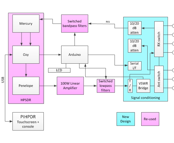
I think there's a good year's work in there! I'm thinking the signal conditioning will be one PCB, and the preamp/attenuator another; that splits the work into manageable chunks.