
OK, not a vey good photograph.... but at least you can tell it's not photoshopped!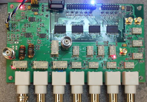
The board contains:
- At bottom left, relays to select 3 antenna inputs
- At bottom right, relays to select RX out and 3 aux RX inputs
- On the right, relays for 10dB and 20dB attenuators on the main RX path;
- In the centre, relays for 10dB and 20dB attenuators on the 2nd RX path;
- At centre left, a VSWR bridge;
- At top left, buffer amplifiers and rectifier for VSWR and forward power detection;
- At top centre, a 32 bit shift register and 12v switched outputs to the TX and RX filters.
I've been able to go through the whole board function and verify it, using the Arduino in debug mode to set the various register settings. It appears to be fully functional. The VSWR bridge provides a coupled path to the receiver output for TX linearisation; the coupled signal is -56dBc and 3-dB above breakthrough which is good.
Some measured performance figures: the TX path loss is < 0.2dB; RX path loss < 0.8dB. The relay isolation isn't great - about -40dB when the paths are 50Ω terminated; that's comparable with figures I've seen on the internet for other projects. It does mean that we need zero power (in noise) from the TX linear amplifier
when in receive mode!
I had an interesting issue with the VSWR bridge. I used my FT450 as a "calibrated transmitter". all was well at 10W and 20W. At 50W the forward power reading started rising and kept going up. Ages later I found that the toroids were cracked. The cause was traced to the 1 turn winding carrying the TX power: I'd wrapped that tightly around the toroid, not put it through the centre of the toroid. That meant all of the magnetic flux was concentrated in one part o the toroid, overheating it. Rewound toroids with the wires through the centre have been fine with no heating. I've used 20 turns, giving -26dB coupling (1/20 voltage). Only the 1T winding in the TX path has appreciable current in it; the 20T windings can be 25SWG or smaller wire.
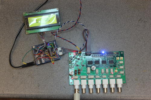
The Arduino now gives an indication of the board settings in RX and TX, and have over temperature and over VSWR trips. It has forward power and VSWR displays, and bargraphs. The latter are a little annoying because the LCD flickers when it is redrawn; a proper graphical LCD would be getter. As a way to check the settings, it's fine; as a user interface it would be poor.
3 months start to finish, including writing the Arduino code. Not bad. Next - Power up the Red Pitaya. I need to get that working with pihpsdr and interface it to the Arduino before I can move forward.
Here you can see the whole, with the Arduino centre left under its shield. The latter is hand wired on a proto board, but I have a schematic and PCB template captured.
Surface mount assembly has been a mixed bag. The passives are easy: tin a pid; tack one end down while holding with tweezers; solder the other end; re-do the 1st end. But the ICs, even with 50 thou lead pitch, have caused me grief. The 32 bit shift register (80 pins total) took a long time to get right! Ultimately it's doable with simple soldering iron and magnification with these devices. The ADC/DAC conditioning board will have 20 thou (0.5mm) leadpitch ICs; I'll need a proper reflow approach by then. A simple USB microscope (£11 from ebay) makes inspection easy; mine has 50-500x zoom but 20x-80x would have been better.