
I started off with a Red Pitaya module purchased from ebay; unfortunately it wouldn't boot and execute code. So I now have a new StemLab 125-14 starter kit, and it powers up OK and get to the point where the red LED blinks (indicating processor heartbeat). I can't get the recommended web address to work (RP-xxxxxx.local) but my router has given it an IP address and connecting to 192.168.0.9 works fine. I was able very quickly to download and install Pavel Demin's HPSDR transceiver code.
For some reason, pihpsdr won't connect to the board. It recognises it in the discovery process, and pihpsdr starts up, but I just then get a blank screen which is what happens if no sample data has been transferred. The same happens on the Raspberry pi and on an x86 laptop; I see some hours ahead with wireshark! It does connect however to PowerSDR, so I've been able to have a simple receive and transmit function operating.
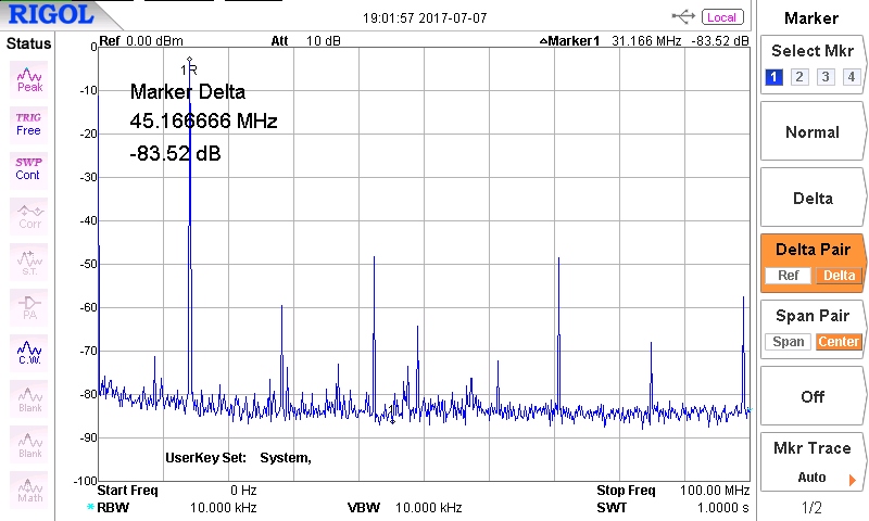
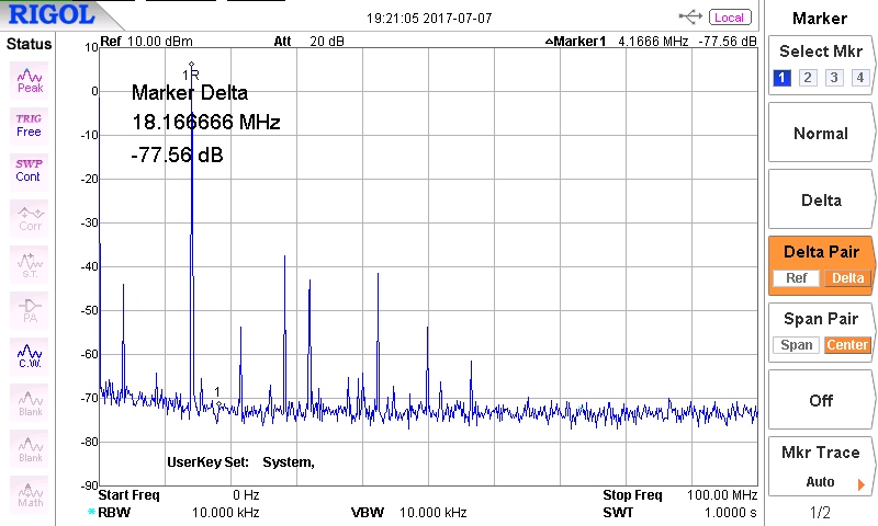
The Red Pitaya when used for SDR has a reputation for poor TX spurious, which was something I wanted to check out early. I've used PowerSDR in "tune" mode and collected a spectrum analyser plot for each band. There are some line spurious other than harmonics present. On 1.8, 3.5 and 7MHz bands the spurious are comparable in level with those from a Penelope board; the line spurious would be removed by a TX low pass filter anyway. but on 14MHz and above, I got spurious signals below the wanted frequency which wouldn't be filtered out (in this case at 3.6MHz, see plots). Other than that the noise floor is maybe 3dB higher - probably due to oscillator jitter rather than PCB layout.
(14 MHz TX signal from Penelope PCB)
(14 MHz TX signal from Red Pitaya, with spurios at 3.6MHz)
So was this a function of the hardware, or the FPGA code? Well, there's a signal generator application; load and run that, and with a 14MHz output signal there is no sign whatsoever of a spurious signal below the wanted signal. So there is no problem with the Red Pitaya hardware. My guess is that it is an artifact of the interpolating filters Pavel has used to convert the sample rates: RP has a 125MHz clock while HPSDR uses 122.88MHz. I suspect the solution will be to use a 122.88MHz crystal (122.88MHz VCXO are readily available at low cost), and have simpler non-interpolating filters. An interesting test, if I can find out how to do it, will be to run one of Pavel's other programs with the current clock and conventional filtering. (Note I've got to the bottom of this; it has nothing to do with interpolating filters, and is now resolved - see here)
So my immediate challenges are:
- Resolve why pihpsdr won't take samples from the Red Pitaya;
- Interface the RP C code to the Arduino, with the Arduino posing as another I2C register;
- (in slower time) investigate changing the FPGA code to use a different oscillator source.
The first two of these are tasks for this summer; the third might well take a few months - but "learning and doing" FPGA development was what I wanted to achieve.