
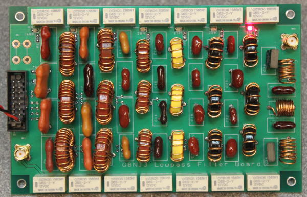
Nothing to do with software defined radio, but…. every transceiver needs TX filtering, and mine will be no exception. You can buy filter boards, and my original intent had been to re-use one from ebay salvaged from a scrapped transceiver. Then curiosity took hold. I’ve ended up with a fully working filter board, controlled by my Arduino, but as usual there’s been a story along the way!
It’s generally accepted that an HF transmitter needs 7 low pass filters, although the exact splits around the WARC bands does vary. Most seem to be 5 pole filters – typically three capacitors and two toroidal inductors. Air cored inductors are sometimes used for 50MHz. The power dissipation is small (because you’re trying to pass HF, and remove less than a watt of harmonics) but the capacitors do see a high voltage (around 70 volts RMS at 100W) meaning you need special capacitors – either high voltage C0G dielectric ceramic, or silver mica. 5 pole filters do give good enough rejection of harmonics if the filter cut-off is just above the band, but using a filter for two bands (eg the 14MHz filter also covering the 10MHz WARC band) makes this harder. I decided to use 7 pole filters, on the basis they roll off faster.
There are lots of free computer programs for filter design. The two kinds are filter synthesis (i.e. designing the inductor & capacitor values for a given filter specification) and analysis (where you calculate the actual behaviour of a set of components). You need both. I used RFSim99 because I preferred its user interface, but QUCS is regarded as a standard. (I found filter synthesis gave slightly different results between the two, but the analysis simulations were identical).
My design approach was:
- Use filter synthesis to find the idealised component values needed, setting the “corner” frequency of the filter above the highest TX frequency. (I aimed for the -3dB point being 1.4x max frequency). This gives you a set of component values, that won’t match anything in a catalogue.
- Find the nearest “real” capacitor and inductor values. Capacitor values are usually E12 1-1.2-1.5-1.8-2.2- etc values. Inductor values depend on the number of turns wound on your chosen toroids. I started with a plan to use T50-2 and T50-6 toroids; in the end I also added T68-2 at low frequencies (the larger core allowing more windings) and T50-10 at high frequencies (the lower permeability allowing more turns). I also opted for air cored inductors at 50MHz, but this may be a sub-optimal decision. You can find inductor calculators here, and a table of toroid inductances here.
- Use filter analysis to find out the true behaviour of the circuit you’ve arrived at. My aim was <0.1dB in-band loss, ~40dB loss at 2nd harmonic and 60dB loss at 3rd harmonic. If the filter doesn’t meet these specs, change the components values a bit, change toroid cores or move the “corner” frequency a bit. Remember that the PCB traces may add ~25nH inductance, so make the target inductance slightly smaller than needed. You can find inductor calculators here, here and a table of toroid inductances here.
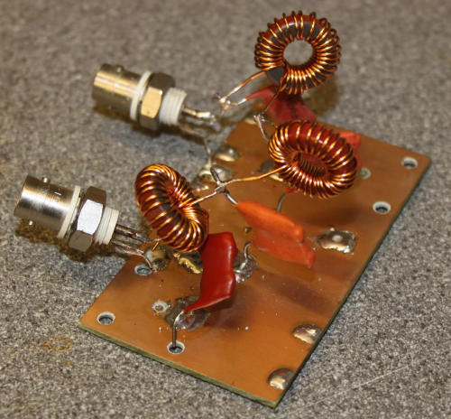
- Solder them together and measure the performance. I prototyped every filter before soldering into the PCB. All the inductors use 22SWG wire, which will happily carry the 1.4A RMS current at 100W.
I only had problems with one filter – 21MHz – which was eventually traced to having used the capacitors from the 14MHz filter. The 50MHz filter has been optimised by compressing/expanding the windings to adjust the inductance, but it isn’t perfect.
The whole seems to be a good solution. I’ve measured the in-band insertion losses, and the attenuation at each harmonic. I also operated each filter with 100W of CW “key down” to see if power dissipation was a problem. Nothing seemed to warm up, so imminent destruction if the filter isn’t likely.