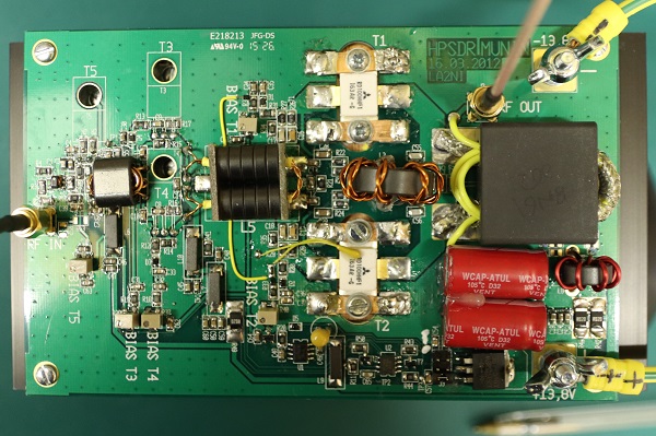
A long time in coming, I suspect... Munin is the 100W amplifier developed for HPSDR. As well as the 100W final output stage, includes a driver stage and a pre-driver stage. The pre-driver isn't normally assembled (and I've had to guess at some of the component values); but when it is, the amplifier apparently needs around 0dB in for 100W out. I collected the parts to make the Munin over last Autumn and completed a lot of the assembly at Christmas.
You can find a lot of information about Munin with links to all of the design files etc here.
There was nothing particularly difficult with the construction, once I had all of the components. The ferrites, and RF output transistors, came from US suppliers RF Parts and Kits and Parts. The drivers (RD16HHF1) came from ebay. The "middle" RF transformer was made from ferrite beads and copper tube, rather than buying the CCI transformer - simply because the shipping cost was approx. 3x the transformer cost. My ability to tap holes in aluminium has been brought into question - several holes ended up with stripped threads. 3 half turns clockwise, one half turn back was the rule and I should have stuck to it.
Testing got off to a poor start: I was unable to apply power to the board with it appearing dead short to the power supply. By removing the ferrite beads carrying power to each stage individually, I was able to isolate the problem to the intermediate stage. It turns out that the RD16HHF1 devices from Ebay were not genuine Motorola devices: instead they were diodes. The data code markings were different from what everyone's image show; I think they were counterfeit devices. I've never once had that before. Two new devices that were by now ex stock in UK, and the amplifier worked fine.
I've been able to prove I can get 100W from the amplifier. I haven't yet done linearity tests; I've equipped myself with a dummy load to which I've added a 30dB coupler ready for that (see below). I really don't have any more excuses... I've found that PowerSDR can generate a two tone signal, and with approx. 10dBm PEP each carrier is at 4dBm. That's correct: sometimes they will add in phase, doubling the voltage and hence quadrupling the power. Once I've determined the power required for 100W out, I can make the attenuator board and package everything up. Oh.... and fix the software bug that makes the Arduino crash; my money is on an array reference out of range.
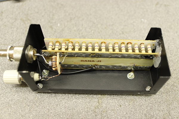
I've made a modified dummy load: start with a 100W dummy load from ebay, and ass a 30dB coupler and you have a load capable of taking full power and giving you a signal it's safe to feed into a spectrum analyser. the 30dB coupler is simple an FT50-43 toroid, with the input power on a single wire through the centre of the toroid and 32 turns of 25SWG wire wound onto the core as a secondary.