
This was made from the excellent Radio-Kits kit after I came across it, entirely by chance, at a rally. It measures forward and reverse power over the HF bands and displays its findings on an LCD display. There are various options for how the data is displayed. A microcontroller does all the processing, and includes a "peak hold" function to display PEP values.
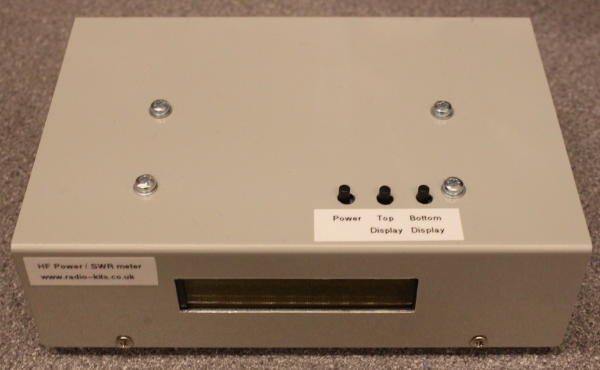
The kit is complete and simple to build. There is a PCB for the processor and analogue gain stages, and a separate PCB for the HF sampling head which uses ferrite current transformers to sample forward and reverse power. i assembled mine into a small aluminium box with the PCB just under the lid (as intended): three miniature PCB mounted switches that were on the "back" of the PCB then poke through holes in the lid. The LCD display is mounted at right angles through a single-in-line connector, and mounts behnd the front panel. Templates are provided to mark the panel cutouts required, making the whole process painless.
I calibrated my meter against a spectrum analyser after some careful "double checks" that I had attenuators in the right places. The measurements were very linear, and essentialyy flat from 1.8 to 30MHz. I needed to change the caliration from the "setup" calibration suggested by the suppliers, which I found to be about 2dB low. After calibration - excellent performance!