
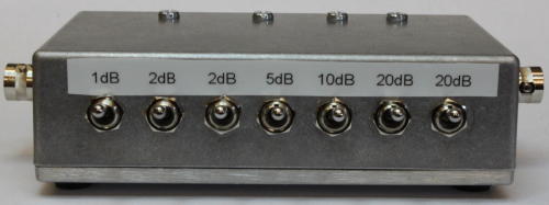
Everyone should have one! A switched attenuator is incredibly useful when making RF measurements, and they are very easy to make. I have used 7 sections switched as 1dB-2dB-2dB-5dB-10dB-20dB-20dB allowing up to 60dB attenuation.
The component values aren't exact "E12" resistor values, so I've used two resistors in most places and used "pi" attenuator elements. A calculator for resistor values can be found on the RF Cafe website. For some reason I couldn't execute their calculator, but the equations are also available there and I put them into a spreadsheet instead. Download the complete circuit diagram: {phocadownload view=file|id=12|target=s}
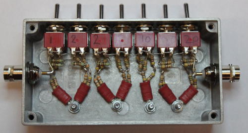
At HF, this can be constructed simply using DPDT toggle switches and 1/4W leaded resistors. Mine is assembled in a small diecast box approx 100mm long; the inside view is shown. It's hard to go too badly wrong with this!
Performance at HF is excellent: much better than I expected. Here are some measured results. All of the attenuators are within 0.2dB of their intended values. There is a slight rolloff with frequency, reavhing 0.2dB at 30MHz and 0.6dB at 80MHz. The attenuations are all essentially flat to at least 80MHz, although the input VSWR edges up abpove 30MHz.
|
Frequency |
0dB | 1dB | 2dB | 2dB | 5dB | 10dB | 20dB | 20dB |
| 5MHz | 10.2 | |||||||
| 10MHz | 0.05 | 1.06 | 2.1 | 2.08 | 4.9 | 10.1 | 20.1 | 20.1 |
| 20MHz | 10.1 | |||||||
| 30MHz | 0.2 | 1.2 | 2.2 | 2.2 | 5 | 10.2 | 20 | 20 |
| 40MHz | 10.3 | |||||||
| 50MHz | 10.4 | |||||||
| 60MHz | 10.4 | |||||||
| 70MHz | 10.5 | |||||||
| 80MHz | 0.6 | 1.6 | 2.7 | 2.7 | 5.5 | 10.6 | 19.5 | 19.8 |
If I ever need to do VHF measurements, I'll make another one with the same resistor values on a double sided PCB with PCB mounted switches and the "through" path on a 50Ω microstrip line. Until then this one is fine at HF.