
A dummy load with a difference: mine also includes a 30dB coupler, to sample the incoming power.
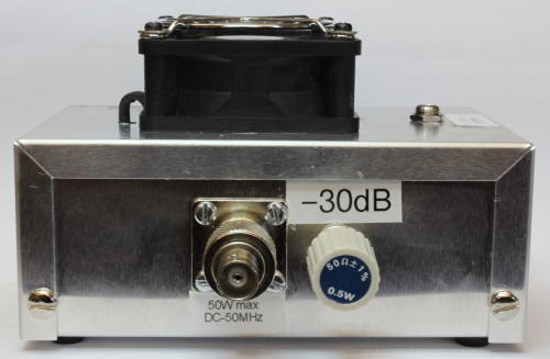
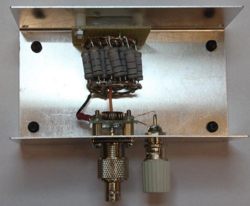
The dummy load is constructed with 20 off 1K 3W carbon resistors. On the face of it the load should be OK up to 60W. Just to make sure they don't get overheated I've also added an old PC processor heatsink fan onto the top of the case, to provide "forced air" cooling.
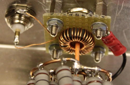
The 30dB coupler is simply a toroidal transformer using an FT50-61 ferrite core. The wire from the input RF connector to the load passes through the centre of the core, and 32 turns of 25SWG wire are wound on the core. This acts as a current transformer, with output current into 50Ω of 1/32 input current. This is almost exactly a power of 0.001 times the input power, or -30dB. That can be used as a "sample" point for spectrum or power measurements. I leave it terminated with a 50Ω resistor when not being used, although frankly it would make little difference to the match.
In practice the 30dB sample point is flat up to 50MHz. Its coupled loss falls to about -27dB at 80MHz and rapidly rises above that. Clearly a different toroid core would be needed for high frequencies.
| Frequency | Coupled port loss |
| 10MHz | 30.3 |
| 20MHz | 30.5 |
| 30MHz | 30.5 |
| 40MHz | 30.2 |
| 50MHz | 29.6 |
| 60MHz | 29.1 |
| 70MHz | 28.4 |
| 80MHz | 27.8 |