
This follows on from the earlier attempt! My first ATU wouldn't tune at the higher frequencies, because there were not enough taps on the inductor to select small values of inductance. time to do some design, and not guesswork!
I've noted that some designers use two inductors - one for low and one for high frequencies, I found an on-line T match simulator program and worked out inductance values both to feed a 50Ω load and to feed my longwire antenna. This suggests that the inductance values need a lot of choice at the "low inductance" end, for example:
0.2, 0.3, 0.4, 0.5, 0.6, 0.8, 1.1, 1.5-2, 4-5, 16-20 (all microhenries)
I shortened my 38mm inductor to 28 turns withs taps at 7 and 15 turns; and I wound a 13 turn inductor on a T130-2 iron dust toroid core. That has taps at 1,3,4,5,6 and 9 turns.
The results now lets me match well on all bands including 50MHz (I've no idea how much power is being coupled out, as opposed to being lost in the toroid though).
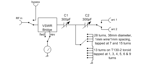
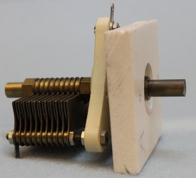
Sourcing the capacitors was a problem: I can't find anyone that makes variable capacitors any more! I purchased some from J Birkett in Lincoln, but these had very small air gaps which would limit the usable power. Eventually I found a pair of 300pF (ish) capacitors at a Rally. The "T" match design requires that the capacitors be insulated from ground. I mounted mine onto a think piece of plastic material with a partly bored hole for the mounting nut. The knobs are calibrated 0-6, with 0 being full capacitance and 0 being exactly unmeshed.
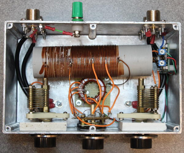
The VSWR bridge was originally to be home made, but I'd purchased a universal VSWR bridge kit while purchasing toroids and in the end I used that for convenience. A tiny "battery indicator" moving coil meter was used for tuning indication. It isn't intended to provide a calibrated measurement. I've adjusted the forward and reverse power meters to give a mid-green indication with 5W.
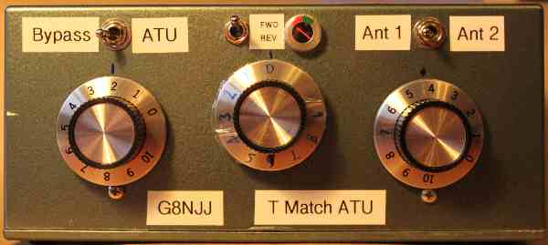
The ATU was assembled into a diecast box, and spray painted. Mysteriously the colour looks remarkably like that of my old car.
Loading into 50Ω and into my longwire antenna was as follows (recorded as C1 - L - C2). These values are up on the wall, and are remarkably accurate when I "revisit" a band allowing simple tuning:
| Frequency | 50Ω | End fed antenna |
| 1.9MHz | 1.2 - 4 - 1.2 | 0.2 - 4 - 3.2 |
| 3.65MHz | 0.8 - 1 - 0.8 | 2 - 1 - 1 |
| 7.05MHz | 1 - 3 - 0.9 | 4 - 2 - 1.8 |
| 10.1MHz | 2 - 5 - 2 | 4.6 - 3 - 4.1 |
| 14.2MHz | 1.5 - 7 - 1 | 3.7 - 7 - 3.9 |
| 18MHz | 1.1 - 7 - 0 | 4.5 - 7 - 2 |
| 21.2MHz | 2.4 - 8 - 1 | 4.9 - 7 - 4.2 |
| 24MHz | 2.5 - 8 - 0.8 | 5.3 - 8 - 4.3 |
| 29MHz | 2.5 - 8 - 1.8 | 4.7 - 9 - 4 |
| 50MHz | 5.2 - 9 - 5.1 | 5.8 - 9 - 5.3 |
A good outcome; I've declared it "finished".