Mike M0ZDZ reported that his beloved FT1000 had failed during the ARRL 10M contest last year. He thought it had good power output on other bands, but not on 10 metres. I wondered if that was a failed low pass filter or relay in the LPF board. However when I opened it up there was no damage evident to the LPF, and there was only 2 watts of output power on any band. That indicates PA or power supply failure; the PA supply remained at (I think) 31V so that wasn't the problem.
You can still download the service manual for this radio. The PA is quite different from the FT1000MP, so you do need the correct one. I didn't write down where I downloaded it from, but look for "FT1000D_serv.pdf".
The PA itself isn't easily accessible, You remove the metal "cage" over the PA and power supply then remove both heatsinks as a pair. Unfortunately there are a lot of connectorised wires to both, so you need to draw a diagram showing what went where. The PA includes a pair of driver transistors (MRF486) followed by a pair of final transistors (MRF422). The fault could be any of these 4. I desoldered the PA transistors and bent up the legs, which were east; I could then use a multimeter to check that I got a diode junction from B-E and B-C on each transistor. Those were OK. Doing the same for the PA was a lot harder because of the copper tabs being much larger, but having done that I found that one transistor just didn't have en emitter connection - the bond wire must have failed.
Mike was keen to attempt repair, so we purchased a new pair of MRF422 from Mouser electronics. removal and replacement was quite simple, using new thermal component underneath and to bond the temp sensing diodes. The alignment process is tricky, because you need to monitor the voltage across a couple of resistors (R7014 for the driver stage, R7027 for the finals). There aren't any test points provided for this. The driver alingment was simple, but the finals always had excessive bias current (with a measured voltage of 30kmV minimum, whereas the target id 6mV across R7027). The bias is set by a series combination of a fixed resistor R7025 and variable one VR7002. The manual says R7025 should be 150R, but it was actually 100R; I had to add a further 680R series resistor to get the bias low enough. I've attributed that to the new Mouser transistors (from a second source supplier) having higher gain than the originals.
There are good audio quality reports after doing this. Strictly I should get a 2 tone oscillator and re-check linearity using a spectrum analyser but so far we've settled for checking for signals above and below the operating frequency.
My friend Chris M0KTT has a TS940 transceiver. It is a 1980's vintage unit which is showing signs of age related distress (who isn't...). Chris brought the FT940 to visit when it appeared to be completely locked up: the displays were lit but no frequency was displayed and there was no response to almost any pushbutton. I'd anticipated the problem might be a loose or failed connector, but that didn't seem to explain that nothing functioned.
In the mid 1980's such a radio would have a microprocessor and battery-backed-up RAM. If the numbers in it were rubbish, what would it do? An internet search revealed that the radio had 2 backup batteries: one is on the timer board (visible behind the front panel) but the one we wanted was buried on "Digital unit A". To get to that remove the top lid; then remove the metal right angled panel that holds the speaker (4 screws). Then remove the lid on the unit under that (8 screws I think) and et voila, there's a processor board. It has a Z80 processor (the same as the ZX spectrum used to have all those years ago). And a soldered in lithium battery, which was very dead.
We were able to get a new coin cell holder from Maplin, and soldered that with two flying leads in place of the old one. The required polarity is clearly marked on the PCB. A CR2032 battery (quite possibly the most expensive one on the planet - also from Maplin) was inserted. I encapsulated the holder in heat shrink sleeving then "hot glue"d it to the top of one of the ICs in that module. Then put everything back together.
The radio has a "factory reset" procedure. With the power switched off, press and hold the "A=B" button; then while it's pressed in, turn the power on. All settings were erased, and the radio functions as normal.
There is an unusual feature in this radio - a timer that can turn it on and off automatically at different times. If the "timer" button is presed 9next to the power switch) then the radio will appear totally dead unless it is within a time range at which the timer wants to turn it on. Tht can be very confusing!
There is a service manual available on the internet, which was very helpful. One thing to note is that many of the pages were intended to be a lot bigger than A4. Some schematics for example should be around 60 inches wide: print on A4 and they aren't legible. But if you soom in on the screen they are quite readable and you can do a "screen print" of part of the page.
I'd bought my FT290 through ebay. It was described as "in good condition for age". The seller must have known it had a serious problem with the PLL synthesiser, but chose not to mention that in the description. Oh well: Caveat Emptor.
At power up, the radio behaved OK. But after warming up for 10-15 minutes, it suddenly jumped in frequency. It was around 10KHz off in frequency, and warbled when a constant frequency input was present. I'd also independently discovered that SSB TX audio was badly distorted, so I would need to go through the alignment process.
The first step in the alignment process is PLL alignment. The steps bring all the tuned circuits onto the right frequency: but that didn't cure the frequency error or the warble. When I teact the Intermediate exam syllabus I teach that a digital synthesiser is either on the right frequency, or on a grossly different frequency. This was different: it was about one synthesiser step out. (The synthesiser itself steps in 10KHz steps. For finer tuning, a D-A converter driven by the microprocessor sets a tuning voltage that, via a varicap diode, "pulls" the reference crystal oscillator). My FT290 synthesiser was nearly on the right frequency: so off to the web.
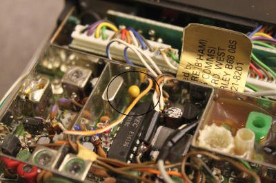
I found on the web that there is a known problem with electrolytic capacitors failing in old FT290s; and John G8MNY had fixed a problem in his FT290 where the synthesiser PLL decoupling capacitor C3055 had failed. http://skywaves.demon.co.uk/technical/Modifications/FT290_690_790_mk1_PLL_fault.pdf That could certainly cause the IC to mis-count, so I added a replacement 10uF tantalum capacitor from pin 1 to ground. Mine is soldered on the component side to the IC leg, and the ground end is soldered to the PLL screening box. Straightaway, the problem was fixed and the PLL alignment could then be completed. Now there is a clear, stable single tone on SSB for a constant frequency input.