
My plan is to use the Red Pitaya board with pihpsdr and my console as the basis for the SDR processing. The Red Pitaya has two 14 bit/125MHz ADC and two 14 bit/125MHz DAC channels; so fully capable of dual receiver operation. Pavel Demin has developed suitable FPGA and ARM software. However it will need a front end. Pretty much all the HPSDR-derived software supports the "Alex" signal conditioning boards as a standard; so I will need something compatible with that. A few hours free in an airport has led to an outline design:
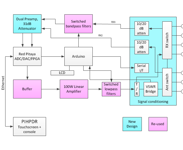
RX and Antenna switching relays - as per Alex ie 3 selectable antennas, 3 alternative RX inputs.
VSWR measurement - the same Stockton bridge as used in Alex
Signal coupler for Puresignal - use the same Stockton bridge. This will mean buffering the forward/reverse power samples before the detector diodes to make sure that no intermodulation is added to the coupled forward power signal going back to the receiver. Tentative buffer choice - Texas Instruments LMH6321 (capable of +/-12V output; likely swing +/-4.7V for 100W).
RX path - 0-31dB switched attenuator as per Hermes; probably an Analog Devices HMC624ALP4E, which is readily available in UK rather than the Minicircuits one. The ADC also needs a preamp, because the Red Pitaya's ADC driver appears to have unity gain; so a 20dB amplifier will be needed. Tentative choice: Analog Devices ADA4895 which is readily available. The Red Pitaya has a high impedance input, and others have reported issues with that. My first plan will be to solder a 50 ohm resistor across its input; if that fails having the 20dB preamp within half an inch of the input connector may avoid problems. I plan to use a set of switched bandpass filters rather than the Alex highpass/Lowpass arrangement. Several seem to be available as kits - I have the Radioshop RV3YF kit from Ebay, and I've previously assembled the Spectrum Communications unit. That's diode switched though, and the loss may be undesirable at higher frequency. A 50MHz LNA may be needed in the awitched filters; I have tentatively selected the minicircuits PSA4-5043+ (25dB gain, 0.75dB NF).
TX chain - the Red Pitaya output will need a buffer amplifier before going through a 100W PA and LPF. I plan to use a "recycled" LPF from Ebay from a scrapped transceiver. Part of the data from the PC is an 8 bit TX amplitude value, used to scale the DAC output. There's a web design with analogue control over the DAC reference current, giving around 20dB dynamic range. Alternatively I can use a 6 bit/0 to 31.5dB attenuator, but the 8 bit control value will need to be converted to a dB value. A lookup table in the Arduino will be simplest. there should also be a tapped off aux output as a transverter drive.
The Red Pitaya has two ADCs, supporting two independent receivers. I plan to make the ANT3 input, if not used for the main input, available as the input for RX2. So I'll need a duplicate attenuator and (possibly) switched bandpass filter set.
Control: most of this will be on a single PCB. Pavel Demin's Red Pitaya code now supports I2C devices to drive an Alex; I plan to interface an Arduino as an I2C slave at a different address and change the C code to support my hardware. This will make the "whole" compatible with the PC/Raspberry PI software, but it will have a slightly different interface to the RP. The registers to drive the relays and attenuators will probably be simple shift registers on the signal conditioning board, to avoid high speed noise generating clocks. I've used ATMEGA processors extensively for my model railway work, so I know the environment. It will also be good for debugging.
The Newest Red Pitaya code supports an I2S codec, giving audio I/O capability from the hardware. That would need a synchronous clock; perhaps giving the Red Pitaya an external clock at 125MHz or 122.88MHz, and a synchronous 12.888MHz clock to the codec, might be possible. An SI570 or triple output SI5351 would give a high quality clock source but I'd need to make sure the code on the ARM processor would execute before the device had been set up. Perhaps the Arduino should control that too.
Finally - I can also use the same signal conditioning with my current HPSDR boards, with an Ozy board providing a USB interface to pihpsdr:
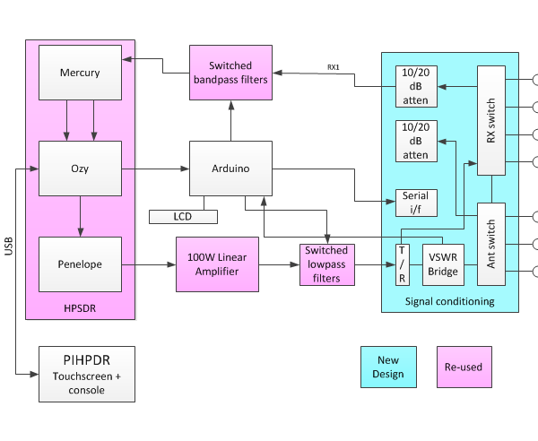
I think there's a good year's work in there! I'm thinking the signal conditioning will be one PCB, and the preamp/attenuator another; that splits the work into manageable chunks.
I had a busy couple of weeks after Christmas. I interfaced pihpsdr to the USB version of HPSDR using an "Ozy" interface board. That didn't seem particularly difficult: the USB protocol uses frames of 512 bytes, while the Ethernet protocol carries a pair of 512 byte frames with the same format. All I needed to do was to queue up USB frames and present the same data to the software. The USB interface code came from "Ozymetis" from the HPSDR SVN repository.
This all worked OK, and John Melton incorporated it into the new build. The new build however introduced some different behaviour, that results in the audio sounding slightly modulated. After a lot of experimentation, I found that the core WDSP radio code operates with blocks of 1024 samples, and it was trying to transfer 1024 audio samples all in one go to the Ozy. That's fine with ethernet, but the USB interface quickly filled the Ozy FIFO and the data transfer stalled. That meant that for perhaps 40% of the time the code was unable to read new RX samples, and sometimes missed some. The solution is to have the USB transmit in a separate thread; that's now been incorporated into John's code base.
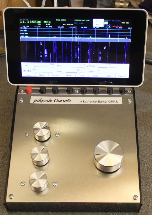
Next - a console. What I'm after is a radio with SDR innards, but a "knob and pushbutton" user interface. The pihpsdr design is certainly a big step in that direction. The Raspberry pi has software-accessible I/O pins, which is how John has interfaced his code. There is a commercially available console, but it's very possible to make your own. See here for an excellent example.
My console uses components mostly supplied by Rapid Electronics. A sloping front instrument case provides the home; the Raspberry pi with touchscreen display sits nicely on top. I've used PCB mounted pushbuttons for the menu buttons, and PCB mounted rotary encoders for the E1/E2/E3 knobs. These have a switch activated by pressing them. All of those are mounted onto veroboard inside the box. My "tuning" encoder came from ebay some time ago, and needs 5V rather than 3.3V (I suspect its LEDs in its optical detectors weren't lighting from the lower supply voltage). Its outputs are open collector, so they don't damage the Raspberry pi GPIO inputs which are not, apparently, 5V tolerant. All of my pushbuttons and encoders have 10K resistor pullups to 3.3V. there's no easy way to know in advance the correct orientation of the A/B rotary encoder wires, and I had all mine back to front so a clockwise rotation reduced frequency/gain etc. Those can easily be swapped in the GPIO menu when you first start the program. I used the largest tuning knob I could find - but it is very light; I plan to add a strip of lead behind it to make it more "spinnable".
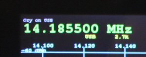
Just to prove I've made some code changes, you can just see the Ozy identified as the radio at the top left of the screen:
So - an SDR radio with knobs and pushbuttons; and I've written a tiny bit of the code. As and when I do get round to the Red Pitaya, I will know in a fair amount of detail what **should** be happening for the data transfers.
What next? I'd like the radio to have the IF shift & width controls on rotary encoders, so they're instantly accessible (in a contest the only controls that seem to be used are the VFO knob and IF shift/width, so I think they need prominence). The signal processing is already there; I think I know how to change the user interface. I had thought of a few other "usability" changes but John had already implemented them in the new "dual receiver" code.
The Raspberry pi runs happily with the same rate set to 192K samples per second, giving coverage of around half of the 20 metre band. If you turn on some of the noise blanker algorithms, you have to reduce the sample rate to 96000 samples per second. A possible future project would be to add an Atmel microcontroller into the console - for example using an Arduino board - and send the pushbutton/encoder settings to the computer through a USB serial port. That would also allow pihpsdr running on different hardware - eg my laptop, which runs at higher sample rates OK - to have the "knob and pushbutton" interface. It's easy to do, but I'd be getting distracted.....
The closest COTS hardware I could find to match my thoughts is the Red Pitaya (linked here). It has a Xilinx Zynq FPGA with dual core ARM processor, dual 14 bit 125MHz ADC and dual 16 bit 125 MHz DAC; potentially a complete radio on a single, credit card sized board. It doesn't have a display interface - instead it uses a web server to a PC, tablet or phone for display.
Pavel Demin has created some SDR applications for the Red Pitaya, so I will have a good starting point (link). One of those is an HPSDR compatible transceiver, mimicing the Metis interface. Another is a complete standalone radio. So I set about following Pavel's example code, intending to load, compile and dabble with each of the examples in turn.
The next problem is: I've never used Linux. Unfortunately for me, all SDR software development seems to be Linux based. I tried using Ubuntu linux in a virtual machine in my laptop; unfortunately the laptop really didn't have enough memory and wasn't upgradeable so I purchased a second hand core i5 laptop from ebay, and installed Ubuntu natively. But going through the compile process - that rebuilt an application, and the PC, and the linux environment for the embedded processor, was heavy going and no one set of instructions was quite right. I needed a simpler learning curve.
I have an old HPSDR board set (Ozy, Penelope, Mercury) with USB interface that I'd bought secondhand, but done nothing with. I looked at the Linux code available (GHPSDR3, GHPSDR3-Alex) but never made them work. I suspect that the vintage of Ozy/Mercury/Penelope meant the protocol wasn't correct. I could get the USB boards working with PowerSDR mrx, but they stopped working after a few minutes... eventually I found something telling me to replace the polysilicon fuses with a piece of wire, because they are known to be under-rated.
The I found pihpsdr, by John Melton G0ORX. This runs on a Raspberry PI2 or newer, and provides the signal processing and user interface for a radio with sample rates up to 9600 or possibly 192000 samples/second. This runs on a processor board costing £30, but with accessible IO and John has interfaced pushbuttons and rotary encoders. Add a touch screen LCD and you have the basis of a radio with touchscreen display AND "proper" knobs and buttons for an affordable price. The only catch: it supports ethernet interfaced HPSDR, but not USB.
Then I found code for "Ozy_Metis_Rpi_Gateway" on the HPSDR code SVN site. That builds a program "ozymetis" that claims to interface USB hardware to ethernet. After a lot of messing around I was able to build and run it on a raspberry PI mk 1, where it flatly refused to work with USB transfer failures. On-line advice was that libusb-1.0 is stable, but not on early RPI units. So I bought a Raspberry pi 3, and the code did run on that when connected to PowerSDRmrx on the PC. I was also able to run it on my laptop. Unfortunately, pihpsdr wouldn't work through it (discovery was OK but no sample data flow).
Christmas week, so some time at home.... I downloaded and learned Wireshark and could look in detail at the ethernet packets. That told me two things: The "START" packet only came out from the raspberry PI after 8 data packets; and the data packets had different control byte settings. The first issue might simply be because UDP packets aren't guaranteed to arrive in the order they were sent; the latter definitely points to different behaviour in the SDR software.
OK, a few changes to the data handling in ozymetis sorted out the first problem. I made a "quick fix" to change the C1-C4 control bytes when C0 is 0; after that pihpsdr worked. I've tidied it up and given it command line options for ethernet interface and whether on not to modify the control data packets. In getting this far, I've learned something about programming under Linux; accessing USB; and I know the USB and "old" HPSDR ethernet protocols reasonably well. It looks likely that different radio programs would need different "fixes" in the protocol converter; so it's unlikely to be a widely reusable generic program.
If I were to be cynical, I could suggest that using recognised international standards for the data interface (eg VITA49.1) might have avoided a lot of this.
My next step is to try to add native USB support into pihpsdr. At the end of that, I'll be well down the road of learning how to do business in a non Windows world. I still haven't got started on the signal processing yet!
I want to commence some work in developing a radio based on Software Defined Radio principles. I’ve been involved with SDR in various guises for a good 20 years, and I’ve never actually written the code to use the technology for radio communications. It’s time to have a go – but I’m not clear where to start.
I’ve been using direct sampling (as opposed to I/Q digitisation, as used in sound-card based SDRs) for years. It would be an alien concept to me to move (what I regard as) backwards. So I’m expecting direct sampling and spectrum generation; a high speed ADC covering the whole HF band, and either a DAC or DDS doing the same for replay. I’m attracted to the DDS route.
User Interface
One of my foibles is that I don’t want to be using a PC as the principal user interface. I’d like a software defined receiver/transceiver to have a user interface such as you associate with an HF radio – knobs, S meter and a spectrum display rather than a VGA screen. There’s no technology reason why SDR needs the PC; I want the PC to be an extension beyond the basic “box”. The “console” unit announced by Flex is a step in the right direction.
Use of Standards
I bought a secondhand board set for HPSDR. That could tick some of the boxes, but it’s already obsolete. Any amateur developed project of this sort will take several years. It's a fact omf modern DSP life that the ADC/DAC parts of such a project will have a lifetime of many years, but the processing will be obsolete in 18 months. I’d like to look at separating the ADC/DAC side of the project (that is specific to the amateur, HF operation) from the FPGA based processing (which is non application specific). The way to do this is through standards. there are already many relevant standards in existence; the Amateur community doesn't need to invent new ones, necessarily.
Hardware standards are relevant to separating the ADC/DAC from the processing. Perhaps having ADC/DAC etc on a mezzanine card connected to an FPGA processor board through a standard interface would allow the FPGA part to be updated by buying a newer commercial product, leaving the amateur community supplied hardware being just the data conversion. An ADC/DAC board with an FMC connector, plugged onto a Zedboard FPGA board, would be an interesting way forward. The processing side is commercially supplied, manufactured in huge quantities and supported by a much larger community. FMC is an open standard, and would allow the processing hardware to be updated to newer commercial technology without throwing away the amateur community investment. Following the Zedboard idea: suppose my ADC/DAC hardware were plugged onto a Zedboard. I can make a “commercial radio” like unit using the Zynq FPGA and two embedded 32 bit processors, giving me a “radio in a box” type capability. There’s a display driver, to connect possibly to a touch screen display. To connect out to a PC, there is an Ethernet connector.
Data interface standards are relevant to the PC connection. If everyone used the same approach, we'd be able to get to the point where any PC application would work with any radio. VITA49 is a standard for transferring I/Q samples: it would be relevant in this case to pass downconverted samples from the direct sampling receiver and FPGA processor into the PC processor. VITA49 is a "lightweight" protocol designed not to add much overhead. The soundcard interface standard from the PC world could also be used, but supports much lower bandwidth channels.
A Project concept
Features I’d like to aim for include:
-
Direct sampling to cover the HF band
-
Simple hooks to add transverters to low microwave bands
-
A “user interface” with knobs, simple screen etc to the point of the overall unit “looking” like a conventional crystal filter based radio
-
“Standard” signal processing on the front panel (e.g. filter width, IF shift, simple notch filter)
-
The main tuning knob to be a high quality 1000 step per revolution unit, like you get with FT1000 class radios
-
100W RF, or (preferably) very simple connection to external linear with ALC etc
-
Resistant to obsolescence through use of standards
-
Standards based interface to a PC for further processing beyond that in the box
-
Standards based hardware implementation
-
Ideally, the commercial suppliers would take the same standards approacvh at the edge of the box, for onward conneciton to a PC. The Elad FM Duo is a commercial product that has some of what I’m after; its connection to a PC is rather limited though, as far as I know with a sound card type interface. The Icom IC7300 has been announced since I started looking at this, and if it had an ethernet port with a standards based interface to sample data I'd get one. Unfortunately, they didn't provide that feature.
Does anyone have ideas/suggestions?
At last - some Software Defined Radio kit in the shack. That's why I got back into Amateur Radio - time to get on with it.
I wanted some kind of full-coverage HF receiver. I have a softrock transceiver kit, but that only covers a few bands. Eventually I realised that the Radio Kits "Hunter" kit was a 1.8-30MHz receiver even if it is badged as a panadapter.
It's hard not to be impressed by the completeness of the kit. It includes the case, the wire and the solder. If you were to argue it should include more, you'd be asking for the PC to be included or so it seems. There are templates to mark the holes for the front and rear panels, and pre-designed artwork for front panel labels. I was able to laser print mine onto a form of "sticky back plastic". The PDF file provided has zero margins, and most printers will clip. You can tell the PDF reader to centre the image; 5mm margins would have given me more flexibility to use the rest of the A4 sheet. But never mind!
Most components are surface mounted. The components are all bagged so there's only one of each visibly different component type in each bag. Within one bag you might find one value of surface mount resistor, one value of surface mount capacitor and one semiconductor. This makes it very very hard to misplace a component. It's still possible to "ping" them across the room if you aren't careful in removing them from the tapes the hold them; in my case a hard wooden floor made it retrievable but carpet wouldn't.
With a good soldering iron, a magnifier and the solder provided you shouldn't have too much trouble. My only caution is that on the "ground" ends that are soldered to a large copper area there are no thermal reliefs, so you need to pour in a lot of heat to flow the solder. I did end up with several resistors not connected at one end.
Once assembled: time for test. Because of the aforementioned soldering issues, I had two faults to resolve. One was in the power supply, and picked up pretty quickly. The other was in the Quadrature Sampled Detector (QSD): this needed me to go round with an oscilloscope until I found that the QSD inputs were all biased to 4.6v not to 2.3v. The debugging method offered by the supplier is to use a multimeter to record all DC voltages; this approach WOULD have found that fault but I do like chasing signals.
One of the "setup" tests is to check the TX/RX relay when driven with RF from a transmitter. I set my FT817 to minimum power setting (0.5W) and that did NOT trip the relay. Setting it to 1W resulted in the board operating as described. The instructions do say to feed it with 1W+ of RF, so it does indeed do what it says on the tin.... I may look eventually at the circuit concerned to see if it can be made a bit more sensitive. Im not in a rush as I expect to use this as a receiver, probably on the IF output of a spectrum analyser.
OK, so I have a working radio sensor.... time to play with the PC, software and soundcard. That's a separate story, and as I discovered far more entertaining. If there's one thing this kit could use, its's a better "quickstart" into getting all of the necessary software up and running. But that, I suppose, is where users like me come in! I will be writing more on this subject, just as soon as I've got to the bottom of the issues concerned.
From a software perspective the board behaves exactly as a Softrock receiver. If PC SDR software supports a softrock with USB tunied Si570, it will support this receiver. For some programs, you will need to copy an EXTIO DLL file to the software directory; others don't need this.
Suffice to say, as a beginner: start off with the "HDSDR" software recommended. Install everything as described. If you don't have a frequency counter, ignore the calibration process described. Connect to your PC "line in"; if you have a laptop, be prepared for some entertainment making it operate as a "line in" and not as a mono microphone input. Disable any "DSP enhancements" or suchlike offered by your drivers. Sadly, each PC / operating system / sound card combination is going to be different: don't despair - you will be able to get there and you won't break anything inthe meantime.
So far I've had signals demodulated using HDSDR, SDR-RADIO and PowerSDR. The programs are all different from each other in some respects, and I've no idea yet which I prefer. Writing my own is one option but there are man years of work that go into some of these programs! What I'm not yet clear about is how to check the input level as seen by the sound card: it's important that it doesn't get overloaded. My laptops have "microphone" inputs that appear to be stereo, but I don't know the signal level they expect. Some kind of input amplitude bargraph display would be quite useful to know that all is well. I think KGKSDR can do this but I've not tried it yet.
Overall: a thoroughly excellent kit. It's so complete and so well delivered thait would be hard to go wrong. I so so wish this sort of thing were around when I was first an Amateur at age 14!