OK, I've been playing with the Red Pitaya for a few weeks now. I can rebuild all the code from source; I can create the memory cards; I can use it as an SDR.
The issue with pihpsdr hasn't been resolved completely, but I can make it go away: pihpsdr sends 10 ethernet frames of data to the red Pitaya before sending a "start" message. The power SDR program only sends two. If I remove the code in pihpsdr that sends 5 of these "preload" packets, it works fine with the Red Pitaya. This might be a timing issue: the code "as is" runs fine on a virtual machine.
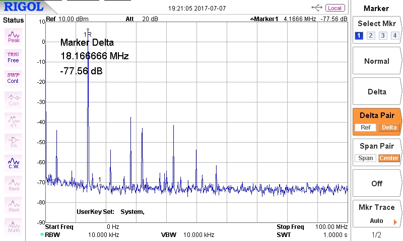
The transmit spurious problem has been resolved. I'd speculated it might be down to the sample-rate-converting filters. But I ran Pavel Demin's "other" transceiver code (which had simple filtering and harmonic sample rates) and that had the exact same behaviour. I found there was a pair of unexplained spurious at +/- 17.85MHz. Pavel Demin sent me 3 code builds to try overnight, and the issue has been resolved by making the FPGA clock synchronous to the ADC/DAC clock (it had been linked through a FIFO).
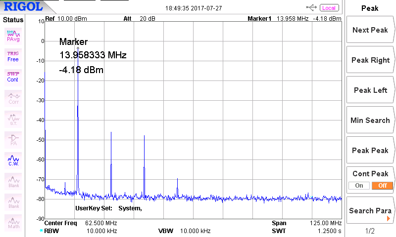
This spectrum is for a 14MHz signal: there are only the harmonics present (which you expect anyway) above a noise floor. That's comparable with what the HPSDR "Penelope" generates.
There has been a huge learning curve - mostly because I insist on understanding what's happening. I've had to learn to build the memory cards, which unearthed a change in behaviour in the linux kernel. I've had to get to the bottom of virtual machine networking, so that my linux VM can talk to the Red Pitaya; the root problem there was an interaction with AVG firewall, which was fixed by an AVG update. I had to figure out how to give my VM access to the USB memory card reader. It's worth pointing out that we call this software defined radio, but the signal processing content isn't that great: the developers of these programs have written a LOT of software.
So, next step: get the Red Pitaya communicating with the Arduino, so I can control my RF front end.
I started off with a Red Pitaya module purchased from ebay; unfortunately it wouldn't boot and execute code. So I now have a new StemLab 125-14 starter kit, and it powers up OK and get to the point where the red LED blinks (indicating processor heartbeat). I can't get the recommended web address to work (RP-xxxxxx.local) but my router has given it an IP address and connecting to 192.168.0.9 works fine. I was able very quickly to download and install Pavel Demin's HPSDR transceiver code.
For some reason, pihpsdr won't connect to the board. It recognises it in the discovery process, and pihpsdr starts up, but I just then get a blank screen which is what happens if no sample data has been transferred. The same happens on the Raspberry pi and on an x86 laptop; I see some hours ahead with wireshark! It does connect however to PowerSDR, so I've been able to have a simple receive and transmit function operating.
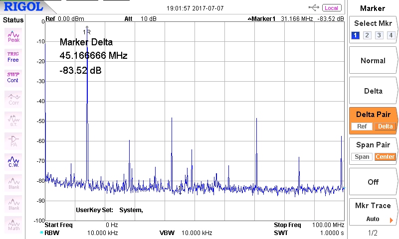
The Red Pitaya when used for SDR has a reputation for poor TX spurious, which was something I wanted to check out early. I've used PowerSDR in "tune" mode and collected a spectrum analyser plot for each band. There are some line spurious other than harmonics present. On 1.8, 3.5 and 7MHz bands the spurious are comparable in level with those from a Penelope board; the line spurious would be removed by a TX low pass filter anyway. but on 14MHz and above, I got spurious signals below the wanted frequency which wouldn't be filtered out (in this case at 3.6MHz, see plots). Other than that the noise floor is maybe 3dB higher - probably due to oscillator jitter rather than PCB layout.
(14 MHz TX signal from Penelope PCB)
(14 MHz TX signal from Red Pitaya, with spurios at 3.6MHz)
So was this a function of the hardware, or the FPGA code? Well, there's a signal generator application; load and run that, and with a 14MHz output signal there is no sign whatsoever of a spurious signal below the wanted signal. So there is no problem with the Red Pitaya hardware. My guess is that it is an artifact of the interpolating filters Pavel has used to convert the sample rates: RP has a 125MHz clock while HPSDR uses 122.88MHz. I suspect the solution will be to use a 122.88MHz crystal (122.88MHz VCXO are readily available at low cost), and have simpler non-interpolating filters. An interesting test, if I can find out how to do it, will be to run one of Pavel's other programs with the current clock and conventional filtering. (Note I've got to the bottom of this; it has nothing to do with interpolating filters, and is now resolved - see here)
So my immediate challenges are:
- Resolve why pihpsdr won't take samples from the Red Pitaya;
- Interface the RP C code to the Arduino, with the Arduino posing as another I2C register;
- (in slower time) investigate changing the FPGA code to use a different oscillator source.
The first two of these are tasks for this summer; the third might well take a few months - but "learning and doing" FPGA development was what I wanted to achieve.
OK, not a vey good photograph.... but at least you can tell it's not photoshopped!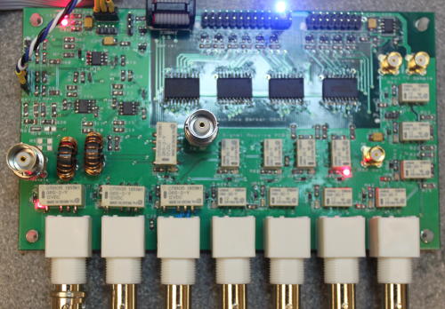
The board contains:
- At bottom left, relays to select 3 antenna inputs
- At bottom right, relays to select RX out and 3 aux RX inputs
- On the right, relays for 10dB and 20dB attenuators on the main RX path;
- In the centre, relays for 10dB and 20dB attenuators on the 2nd RX path;
- At centre left, a VSWR bridge;
- At top left, buffer amplifiers and rectifier for VSWR and forward power detection;
- At top centre, a 32 bit shift register and 12v switched outputs to the TX and RX filters.
I've been able to go through the whole board function and verify it, using the Arduino in debug mode to set the various register settings. It appears to be fully functional. The VSWR bridge provides a coupled path to the receiver output for TX linearisation; the coupled signal is -56dBc and 3-dB above breakthrough which is good.
Some measured performance figures: the TX path loss is < 0.2dB; RX path loss < 0.8dB. The relay isolation isn't great - about -40dB when the paths are 50Ω terminated; that's comparable with figures I've seen on the internet for other projects. It does mean that we need zero power (in noise) from the TX linear amplifier
when in receive mode!
I had an interesting issue with the VSWR bridge. I used my FT450 as a "calibrated transmitter". all was well at 10W and 20W. At 50W the forward power reading started rising and kept going up. Ages later I found that the toroids were cracked. The cause was traced to the 1 turn winding carrying the TX power: I'd wrapped that tightly around the toroid, not put it through the centre of the toroid. That meant all of the magnetic flux was concentrated in one part o the toroid, overheating it. Rewound toroids with the wires through the centre have been fine with no heating. I've used 20 turns, giving -26dB coupling (1/20 voltage). Only the 1T winding in the TX path has appreciable current in it; the 20T windings can be 25SWG or smaller wire.
The Arduino now gives an indication of the board settings in RX and TX, and have over temperature and over VSWR trips. It has forward power and VSWR displays, and bargraphs. The latter are a little annoying because the LCD flickers when it is redrawn; a proper graphical LCD would be getter. As a way to check the settings, it's fine; as a user interface it would be poor.
3 months start to finish, including writing the Arduino code. Not bad. Next - Power up the Red Pitaya. I need to get that working with pihpsdr and interface it to the Arduino before I can move forward.
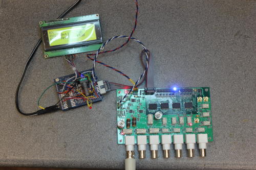
Here you can see the whole, with the Arduino centre left under its shield. The latter is hand wired on a proto board, but I have a schematic and PCB template captured.
Surface mount assembly has been a mixed bag. The passives are easy: tin a pid; tack one end down while holding with tweezers; solder the other end; re-do the 1st end. But the ICs, even with 50 thou lead pitch, have caused me grief. The 32 bit shift register (80 pins total) took a long time to get right! Ultimately it's doable with simple soldering iron and magnification with these devices. The ADC/DAC conditioning board will have 20 thou (0.5mm) leadpitch ICs; I'll need a proper reflow approach by then. A simple USB microscope (£11 from ebay) makes inspection easy; mine has 50-500x zoom but 20x-80x would have been better.
My SDR approach includes an Arduino microcontroller between the Red Pitaya and the various modules that need registers or bit settings. Why? it's a good debugging evironment to work in; and it can drive an LCD display to provide useful information operationally (eg antenna routing, power, VSWR). It means I can make one small set of changes to the red Pitaya code, then make all the updates I need to in the Arduino world.
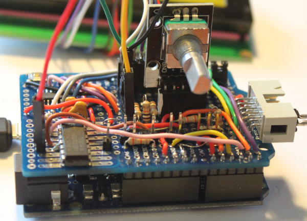
I worked out the interfaces I would need to support and ended up needing just too many wires for the "standard" Arduino Uno. The same board size Arduino Leonardo has two more signal wires available, which tipped the balance. I've then made a prototype shield with all the necessary I'O connectors etc; this looks OK on the top side but looks quite ugly underneath where all the interconnect wires are! The Arduino has connectors for:
- LCD display (6 digital outputs);
- rotary encoder + pushbutton (3 digital inputs);
- I2C interface to the Red Pitaya (2 I2C pins, with 3.3V to 5V level translator);
- Serial clock/shift/load to my external boards (3 digital outputs);
- forward, reverse power, PA current, heatsink temperature inputs (4 analogue in);
- T/R in from Red Pitaya (1 digital input, 3.3V to 5V translated);
- T/R out to hardware (1 digital output);
- Jumper to select debug mode (1 input).
A PCB for this would be more elegant, and possible, but not a high priority if this one works!
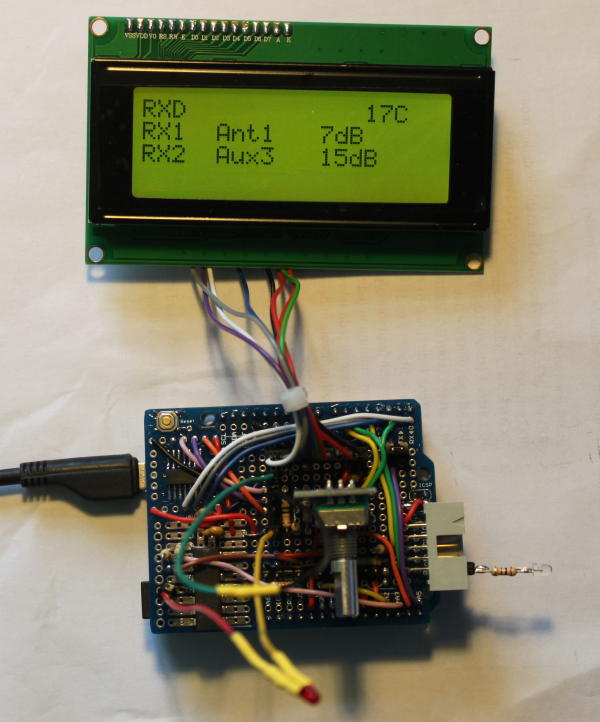
The software presents a user interface on a 4 line x 20 character LCD display. This indicates RX1 and RX2 antenna selection and attenuation; in TX it will eventually present bargraph power and VSWR (I have the code from other projects). Its "debug" mode will let me edit all settings with the rotary encoder, so I can test and debug my hardware. Here it is showing RX, debug mode ("RXD" top left).
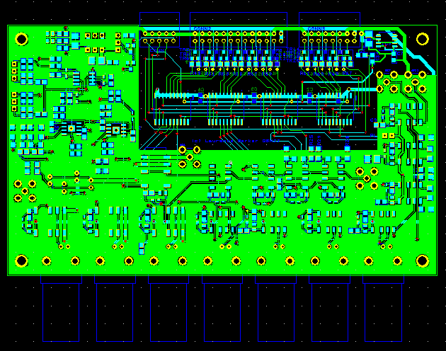
OK, so my first PCB design is complete. This is the antenna switch / routing PCB. It includes:
- Antenna / aux receiver inputs, similar to HPSDR Alex;
- VSWR bridge and buffer
- Signal sampler for Puresignal
- 10/20dB switched attenuators for RX1 and RX2
- Arduino interface to control relays, external filters and a heatsink fan
This will give similar capabilities to the Alex unit, but with external filters. Also it selects a signal path for the second receiver input. While this is being manufactured I will write the Arduino code. That will provide a debug/test interface, but it will be used operationally too.